

 English
 Español
Content
- 1 Product Overview
- 2 Why the Motor Housing Design Matters
- 3 Uniform 1.5 mm Wall for Weight and Thermal Performance
- 4 Material Selection: SPCC, ST12, and DC01
- 5 Precision Forming and Cylindrical Accuracy
- 6 Welded Screw for Efficient Assembly
- 7 Welded Mounting Foot for Stable Installation
- 8 Weld Quality and Long-Term Reliability
- 9 Advantages Compared with Conventional Motor Housings
- 10 Applications and Industry Suitability
- 11 Manufacturing Capabilities Behind the Product
- 12 Engineering and Development Support
- 13 Quality, Capacity, and Supply Reliability
- 14 Installation and Integration Considerations
- 15 Recommended Validation Program
- 16 Customization Possibilities
- 17 Commercial Value for Motor Manufacturers
- 18 Frequently Asked Questions
- 18.1 What is the actual inner diameter of the product?
- 18.2 What are the main dimensions?
- 18.3 Which materials can be used?
- 18.4 Does the housing include a mounting feature?
- 18.5 Is a screw included in the housing design?
- 18.6 Why is the wall thickness only 1.5 mm?
- 18.7 Can the housing be customized?
- 18.8 Is this housing suitable for continuous motor operation?
- 18.9 How does the product help reduce vibration and noise?
- 18.10 What manufacturing processes are available?
- 18.11 What industries can use this type of motor housing?
- 18.12 What information should be confirmed before an order?
- 19 Conclusion
- 20 References
- 21 Product: Inner Diameter 95 Steel Motor Housing
Motor housings are essential structural components in electric motors. They protect the stator and internal electrical parts, preserve concentric alignment, support mounting, assist heat transfer, and contribute to the long-term stability of the complete drive system. Although a housing may appear to be a relatively simple cylindrical component, its dimensional accuracy, material consistency, weld quality, and mounting features can directly influence motor efficiency, noise, vibration, service life, and assembly cost.
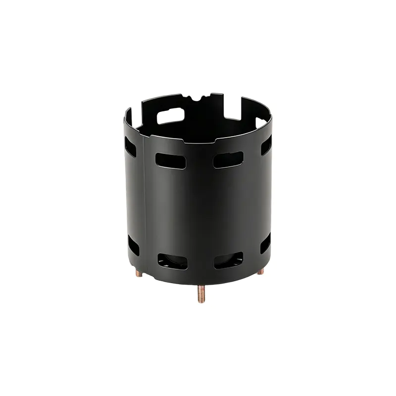
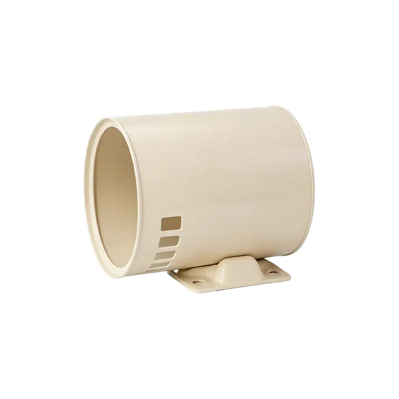
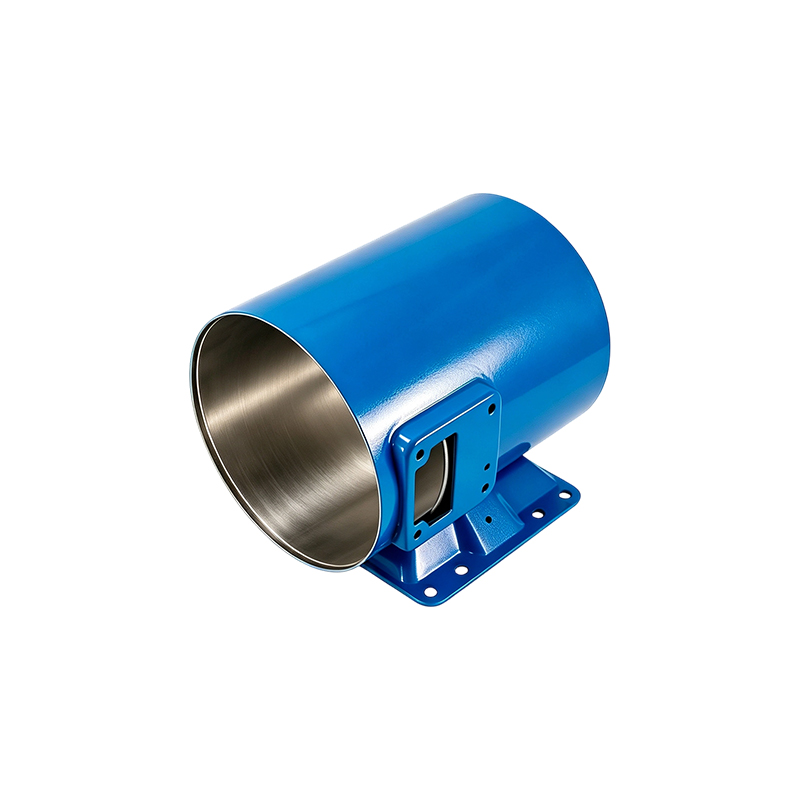
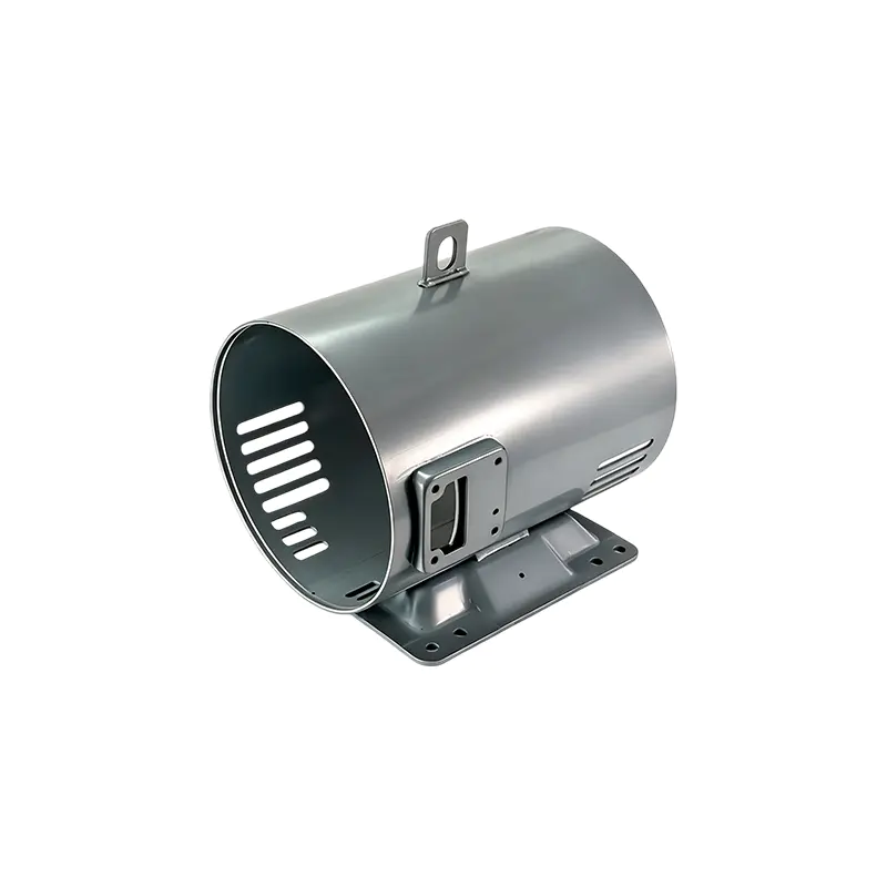
The Inner Diameter 95 Steel Motor Housing is a precision-engineered steel housing designed for compact motor assemblies and demanding production environments. According to the supplied technical information, the housing has an inner diameter of 96 mm, an outer diameter of 99 mm, a height of 113 mm, and a wall thickness of 1.5 mm. Its construction uses SPCC, ST12, or DC01-grade steel, providing a practical combination of formability, strength, dimensional stability, and manufacturing consistency.
This product is especially suitable for applications that require a thin-wall motor enclosure without sacrificing structural reliability. Its compact dimensions support space-efficient equipment design, while the welded screw and welded mounting foot reduce the need for additional processing during final assembly. The housing is manufactured through integrated capabilities covering stamping, welding, machining, assembly, and surface treatment, enabling better process coordination from raw material preparation to finished-product delivery.
For customers seeking a dependable steel motor housing supplier, the value of this component extends beyond its dimensions. The product combines controlled geometry, efficient heat conduction, simplified installation, and robust welded construction. These characteristics can help manufacturers reduce secondary operations, improve production consistency, and build quieter and more reliable motor systems.
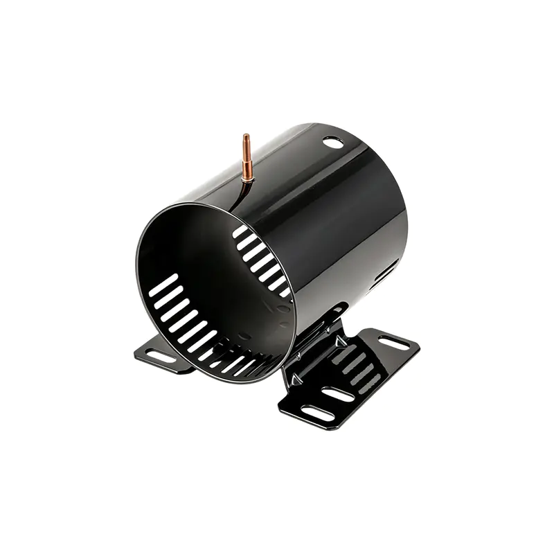
Inner Diameter 95 Steel Motor Housing
Product Overview
The Inner Diameter 95 Steel Motor Housing is a cylindrical steel component developed for the support and protection of motor internals. The product description identifies the component as ID096002. Its principal function is to provide a stable enclosure for the stator assembly while maintaining the required relationship between the stator, rotor, end structures, and mounting system.
The housing has a nominal internal diameter of 96 mm. Although the commercial product title refers to an inner diameter of 95, the available specification table lists the ID as 96 mm. For engineering approval, customers should confirm the final drawing, tolerance range, and production reference before placing an order. This dimensional clarification is important because even a small difference in motor housing diameter can affect air gap control, stator insertion, press-fit conditions, vibration behavior, and final motor performance.
With a height of 113 mm and an outside diameter of 99 mm, the housing presents a compact diameter-to-height ratio. The 1.5 mm wall is thin enough to support weight reduction and rapid thermal transfer while remaining suitable for a rigid steel enclosure when correctly formed and welded. This balance is one of the product’s central advantages: it is not simply a lightweight shell, but a functional structural component designed for assembly accuracy and continuous motor operation.
| Specification | Product Value | Engineering Significance |
|---|---|---|
| Product reference | ID096002 | Supports product identification and production tracking |
| Inner diameter | 96 mm nominal | Defines the stator receiving space and influences concentricity |
| Height | 113 mm | Supports the axial arrangement of the motor assembly |
| Wall thickness | 1.5 mm | Balances low weight, heat transfer, and structural strength |
| Outer diameter | 99 mm | Establishes the external envelope for system integration |
| Material specification | SPCC, ST12, or DC01 | Offers suitable cold-rolled steel characteristics for forming and welding |
| Integrated features | Welded screw and welded mounting foot | Reduces additional drilling, tapping, and mounting operations |
Why the Motor Housing Design Matters
A motor housing performs several jobs at the same time. It must maintain the position of the stator, resist distortion during operation, provide a stable interface with external equipment, help conduct heat away from the active motor components, and protect the internal assembly from mechanical damage. In many motors, the housing also contributes to electromagnetic performance indirectly by preserving the geometry of the air gap between the rotor and stator.
If a housing is too flexible, the motor may experience movement, vibration, or assembly misalignment. If it is too heavy, it can increase the total weight of the equipment and reduce the efficiency of material utilization. If the wall is uneven, the stator may not be centered correctly. If welded attachments are weak, the mounting structure may loosen under repeated vibration. The design of the Inner Diameter 95 Steel Motor Housing addresses these issues through controlled dimensions, a uniform wall, integrated welded features, and a stable cylindrical structure.
The housing’s height of 113 mm provides an axial body length suitable for compact motor configurations. The relationship between diameter and height is important because an elongated housing can be more sensitive to deformation, while an overly short housing may not provide adequate support for the stator assembly. The selected proportions help the component maintain a stable mounting position and support concentric alignment throughout the motor’s operating cycle.
The housing is also intended to reduce unnecessary complexity in downstream assembly. A screw is welded directly to the housing, eliminating the need for an additional drilling or tapping operation in the relevant area. A mounting foot is also welded to the body, providing a defined support point for positioning and installation. These integrated details can improve assembly repeatability and reduce the number of loose parts used in the final motor system.
Uniform 1.5 mm Wall for Weight and Thermal Performance
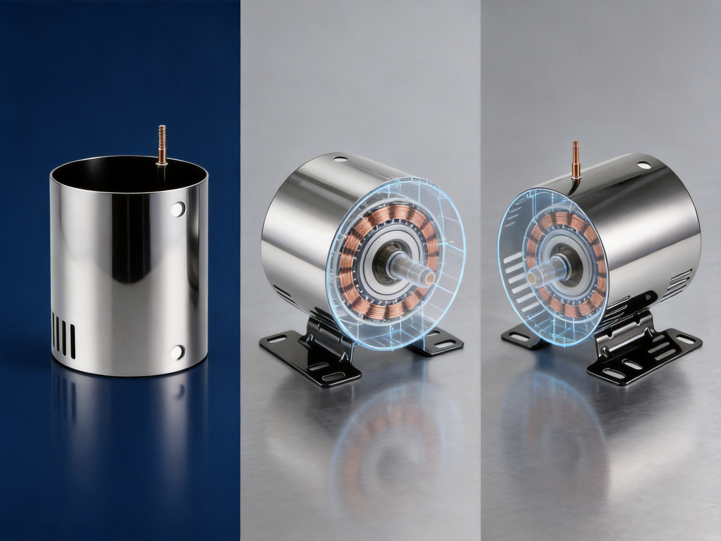
The 1.5 mm wall thickness is a defining feature of this steel motor housing. Thin-wall construction can reduce material consumption and component weight while preserving a compact external profile. In applications where multiple motors are installed in one machine, even a modest reduction in the weight of each motor housing can contribute to easier handling, lower transport weight, and improved system-level design flexibility.
A uniform wall also supports predictable heat transfer. Steel conducts heat away from the motor’s internal structure more effectively when the wall thickness is consistent. Variations in thickness can create uneven thermal paths and localized heat concentration. By using a controlled thin wall, the housing helps distribute heat toward the external surface, where it can be released into the surrounding air or transferred to adjacent structural parts.
Thermal behavior depends on many factors, including motor load, rotational speed, ventilation, surface treatment, internal air movement, winding design, and installation conditions. The housing alone does not determine the final temperature of the motor. However, its material and geometry play an important supporting role. A thin steel wall can provide a short heat-transfer path, helping the motor respond more effectively during continuous or repeated operation.
The design is particularly useful where space is restricted. A thick housing may offer additional strength, but it can increase the outside diameter and consume valuable installation space. The 1.5 mm wall allows the housing to maintain a 99 mm outer diameter around a 96 mm inner diameter, creating a compact envelope for equipment designers. This makes the product appropriate for motors installed inside appliances, industrial mechanisms, compact drive units, and specialized equipment.
Thin-wall steel construction must be managed carefully during forming, welding, and handling. Excessive heat input may cause distortion, while uneven forming pressure can affect roundness. The manufacturing process therefore requires appropriate tooling, controlled welding parameters, fixture support, and dimensional inspection. The supplier’s integrated manufacturing model is valuable because these operations can be coordinated rather than treated as unrelated subcontracted processes.
Material Selection: SPCC, ST12, and DC01
The listed material specifications are SPCC, ST12, and DC01. These material designations are commonly associated with cold-rolled low-carbon steel products used in forming, stamping, fabrication, and general mechanical applications. The exact grade selected for a specific order should be confirmed against the customer’s technical requirements, applicable standards, surface expectations, thickness tolerance, and intended finishing process.
Cold-rolled steel is suitable for this type of motor housing because it offers a smooth and consistent surface, predictable forming behavior, and good availability. These characteristics help manufacturers create cylindrical parts with stable dimensions and repeatable appearance. The material can also support welding operations when the process is properly controlled and the joint design is suitable for the wall thickness.
Material consistency is especially important for motor housings. Variations in yield behavior, surface condition, or thickness may affect forming accuracy and springback. They can also influence the appearance and strength of welded attachments. By selecting recognized steel specifications and applying incoming material inspection, a manufacturer can create a more stable process window and reduce production variation.
Customers may require additional requirements depending on the application. These can include chemical composition documentation, mechanical property data, coating requirements, salt-spray performance, dimensional tolerance, weld appearance, or traceability. The basic SPCC, ST12, and DC01 options provide a practical starting point, while the final material selection should be aligned with the customer’s drawings and validation standards.
Precision Forming and Cylindrical Accuracy
The performance of a motor housing is strongly influenced by its roundness, straightness, diameter, and axial geometry. The stator must be inserted into the housing without excessive interference or unwanted looseness. The internal surface should provide consistent support around the stator circumference. The housing should also retain its shape after welding, handling, assembly, and motor operation.
Precision forming begins with the preparation of the steel blank. The blank dimensions, edge quality, and orientation can affect the final cylindrical shape. Stamping and forming tools must be maintained to prevent uneven deformation, excessive marks, or dimensional drift. A controlled forming sequence helps distribute force across the part and limits local stress concentration.
After forming, the cylindrical body may require calibration or additional shaping to achieve the target diameter and roundness. The correct process depends on the product design, material condition, tooling configuration, and required tolerance. Because the product has a relatively thin 1.5 mm wall, process stability is essential. The part must be strong enough to retain its geometry while still being handled without dents or deformation.
Dimensional inspections may include checks of inner diameter, outer diameter, height, wall thickness, roundness, straightness, feature location, and mounting-foot position. Inspection equipment can include gauges, calipers, micrometers, coordinate measurement equipment, optical systems, and customized checking fixtures. The inspection method should match the criticality of each feature and the customer’s quality plan.
Dimensional control is not only about meeting a drawing value at the end of production. It is also about understanding process capability. A stable process produces measurements that remain within a controlled range over time. This helps reduce the risk of assembly interference, stator misalignment, rotor contact, or inconsistent motor noise. The supplier’s experience in stamping and motor housing production supports the development of repeatable forming and inspection procedures.
Welded Screw for Efficient Assembly
One of the product’s practical features is a screw welded directly onto the housing. This design eliminates the need for an additional drilling or tapping operation in the corresponding location. It also reduces the number of loose components that must be managed during assembly.
For motor manufacturers, eliminating a secondary drilling or tapping step can provide several benefits. It may reduce processing time, lower tooling requirements, reduce work-in-process movement, and simplify line balancing. It also helps ensure that the screw position is consistent from one housing to another. When the feature is integrated during housing production, the customer can receive a component that is closer to its final assembly condition.
A welded screw can also support electrical connection safety when the screw serves as part of a grounding or connection arrangement. The housing and screw must be designed and validated according to the electrical requirements of the finished motor. The contact area, weld integrity, coating condition, torque requirement, and resistance should be confirmed during product approval. The feature is therefore both a mechanical convenience and a potentially important functional detail.
Welding parameters must be carefully controlled because the housing wall is only 1.5 mm thick. Excessive heat can cause local distortion, burn-through, discoloration, or a reduction in dimensional accuracy. Insufficient energy may create a weak joint. Correct electrode selection, fixture design, current control, pressure, timing, and inspection are all important to achieve a stable result.
The welded screw should be positioned accurately so that it does not interfere with the stator, end cover, cable routing, or customer assembly tooling. The integrated manufacturing process allows the supplier to review this relationship during product development and verify the feature before mass production.
Welded Mounting Foot for Stable Installation
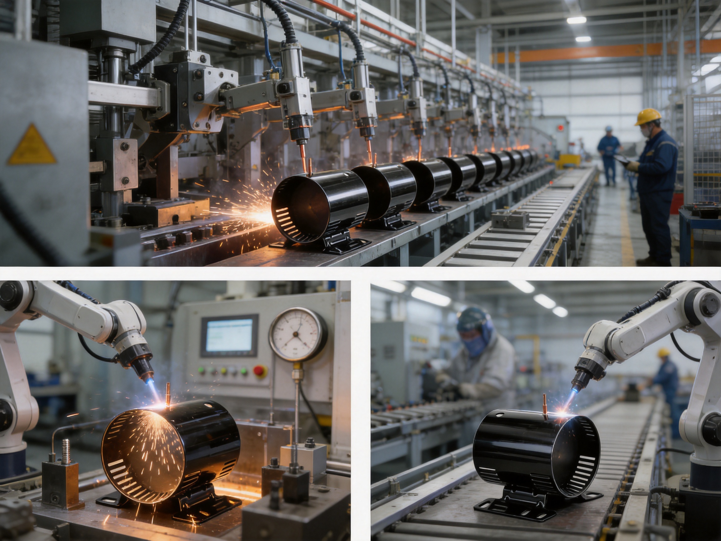
The welded mounting foot provides a defined support point for the motor housing. In compact equipment, installation space may be limited, and a single-point or localized support feature can simplify the mechanical layout. The mounting foot helps position the motor, supports attachment to the machine frame, and reduces the need for a separate bracket or adapter.
Integrating the foot into the housing can reduce the total number of parts in the motor assembly. Fewer components may mean fewer fasteners, less inventory, simpler logistics, and fewer opportunities for assembly error. It can also reduce the overall external dimensions of the motor mounting arrangement, which is valuable in appliances, compact actuators, and integrated drive modules.
The mounting foot must be strong enough to handle the static weight of the motor and the dynamic forces generated during operation. These forces may include vibration, start-stop loading, torque reaction, transportation shock, and repeated thermal expansion. The weld connecting the foot to the housing is therefore a critical structural area.
A reliable welded joint requires proper fit-up between the foot and cylindrical body. Gaps, contamination, inconsistent contact, or poor fixture support can affect joint quality. Automated or semi-automated welding equipment can help maintain repeatability, while visual inspection and periodic destructive or non-destructive testing can verify process performance. The appropriate testing method depends on the customer’s quality requirements and the intended application.
The location of the foot also affects motor alignment. If it is not positioned correctly, the motor may sit at an angle or place unnecessary stress on the connected mechanism. Controlled fixtures and inspection gauges help ensure that the mounting surface, hole position, and angular orientation remain consistent across production batches.
Weld Quality and Long-Term Reliability
Welded joints are central to the reliability of this motor housing because both the screw and mounting foot are attached by welding. High-standard welding technology is required to create firm bonds that resist loosening or detachment during long-term operation.
Motor housings are exposed to repeated vibration. Even when the vibration amplitude is relatively small, millions of operating cycles can produce fatigue stress at weak joints. Start-up and shutdown cycles can create additional mechanical loading. In some applications, the housing may also experience impact during transportation or installation. A properly designed and controlled weld helps maintain the connection under these conditions.
Weld quality includes more than visible appearance. Important factors may include penetration, fusion, nugget size, joint strength, surface defects, spatter, deformation, and consistency. Production controls can include welding parameter records, fixture verification, electrode maintenance, sample testing, visual inspection, dimensional checks, and traceability of material and process conditions.
Because the housing wall is thin, the welding process must achieve sufficient joint strength without damaging the surrounding body. Heat-affected areas should be controlled to limit distortion and preserve the dimensional accuracy of the cylindrical shell. A well-organized welding process can protect both the structural function of the attachment and the precision of the housing itself.
Customers with critical applications may request a process qualification plan, weld inspection standard, sample approval report, or reliability test. These requirements can be incorporated into the product development process. The supplier’s experience in welding assembly provides a foundation for supporting such validation activities.
Advantages Compared with Conventional Motor Housings
The Inner Diameter 95 Steel Motor Housing offers several advantages over conventional housings that require more secondary processing or use less integrated construction methods.
Reduced Secondary Operations
A conventional housing may require separate drilling, tapping, bracket installation, and manual alignment after the cylindrical body has been formed. The integrated welded screw and mounting foot reduce the number of these operations. This can shorten the customer’s assembly route and reduce labor or equipment requirements.
Compact External Envelope
The 99 mm outer diameter allows the housing to support a 96 mm internal diameter while retaining a compact profile. Compared with thicker-wall alternatives, this design can help equipment manufacturers save space and reduce unnecessary mass. The product is suitable for installations where every millimeter of radial clearance matters.
Improved Heat Transfer Potential
The 1.5 mm wall creates a relatively short path for heat to move from the motor assembly to the external surface. When combined with suitable ventilation and system thermal design, this can support more efficient heat dissipation than a heavier, thicker enclosure with the same external function.
Stable Structural Support
The cylindrical steel body provides a continuous enclosure around the stator. The welded mounting foot adds a stable installation point, while the height and diameter relationship supports concentric motor assembly. This integrated structure can help reduce vibration and noise when the product is correctly assembled with compatible internal components.
Material Efficiency
A controlled thin wall uses less steel than a thicker housing while retaining the advantages of a metal enclosure. Material efficiency can contribute to lower component weight, easier handling, and reduced consumption of raw material. The actual economic benefit depends on order quantity, forming yield, production cycle, and customer assembly requirements.
Production Consistency
Integrated manufacturing allows forming, welding, machining, inspection, and finishing to be coordinated under one production system. This can reduce variation caused by transferring semi-finished parts between unrelated suppliers. It also improves communication when design changes or quality issues arise.
Applications and Industry Suitability
The housing can be used in motor assemblies for a variety of industries. Its compact size, steel construction, welded features, and integrated manufacturing approach make it suitable for applications where reliable support and repeatable assembly are required.
In household appliances, the housing may be used in compact motors for ventilation, pumping, actuation, air movement, or mechanical transmission. Appliance manufacturers often require efficient use of internal space, low noise, controlled weight, and stable production quality. The housing’s cylindrical form and welded mounting feature can support these objectives.
In industrial drives, the product may be considered for small motors used in automation equipment, material handling, pumps, fans, and specialized machinery. Industrial applications may place greater emphasis on vibration resistance, dimensional repeatability, mounting reliability, and long operating periods. The welded construction and steel material are appropriate starting points for these requirements.
New energy vehicle systems and related equipment often require compact components with efficient manufacturing and good resistance to vibration. The housing may be suitable for selected auxiliary motors, actuators, cooling systems, or other compact drive functions, subject to application-specific validation. Automotive and new energy customers generally require detailed documentation, traceability, reliability testing, and strict change control.
Special equipment manufacturers may also benefit from a customized housing platform. The basic dimensions can serve as a reference for adjusting attachment positions, adding openings, changing surface treatment, or adapting the mounting method. Any modification should be evaluated for its effects on forming, welding, heat transfer, structural strength, and assembly compatibility.
Manufacturing Capabilities Behind the Product
The company behind this product operates as a professional motor housing manufacturer with capabilities covering research and development, stamping, welding assembly, machining, surface treatment, and final delivery. This full-process structure is important because motor housings require close coordination among multiple operations.
Stamping and Forming
Stamping equipment is used to process steel sheet into accurately shaped components. It supports high-volume production and repeatable forming when tooling, material, and process parameters are properly controlled. For the Inner Diameter 95 Steel Motor Housing, stamping and forming provide the cylindrical body and help establish the core dimensional structure.
Automated Welding
Automated welding equipment can improve consistency in the attachment of screws, mounting feet, and other structural features. Automation helps control position, timing, pressure, and energy input. It can also support higher production efficiency and reduce variation caused by manual operations.
Machining
Machining facilities support operations that require additional dimensional accuracy, surface preparation, hole finishing, or feature adjustment. While the housing is primarily formed and welded, machining may be used where customer specifications require precise interfaces or secondary processing.
Surface Treatment
Surface treatment can improve appearance, corrosion resistance, cleanliness, or compatibility with the final application. The suitable treatment depends on the operating environment and customer requirements. Factors such as humidity, temperature, chemical exposure, electrical contact, and assembly method should be considered before selecting a finish.
Inspection and Testing
Inspection instruments support control of dimensions, material condition, weld quality, and finished appearance. A comprehensive quality system should combine incoming material inspection, in-process checks, final inspection, and periodic reliability verification. This approach helps identify deviations early rather than relying solely on final sorting.
Engineering and Development Support
The manufacturer reports an engineering team with an average of more than 20 years of experience. This experience can be valuable during the transition from concept to mass production. Motor housing development often involves compromises among diameter, thickness, mounting position, tooling cost, weld accessibility, thermal performance, and customer assembly requirements.
During the early design stage, engineers can review the proposed dimensions and identify potential manufacturing risks. These may include excessive drawing depth, sharp transitions, insufficient weld access, attachment interference, difficult inspection points, or distortion after welding. Early design-for-manufacturing review can reduce later changes and shorten the path to stable production.
Prototype production provides an opportunity to confirm fit, appearance, assembly sequence, and performance. Sample housings can be evaluated with the customer’s stator, rotor, end cover, fasteners, and mounting frame. The results may lead to adjustments in tolerance, feature position, weld specification, or surface treatment.
Once the design is approved, production tooling and inspection fixtures can be developed for repeatable mass production. Process documents may include work instructions, control plans, inspection standards, welding parameter records, and packaging requirements. A structured transition helps preserve the approved product characteristics as production volume increases.
Quality, Capacity, and Supply Reliability
The manufacturer has approximately 40 years of experience in motor housing manufacturing and has served more than 50 customers. It also reports an annual production capacity exceeding 5 million units. These figures indicate experience with both product customization and volume manufacturing.
Production capacity is important for customers whose motor programs require stable deliveries. A supplier must be able to support initial samples, pilot orders, ramp-up quantities, and regular mass production without compromising quality. Capacity planning should include equipment availability, tooling readiness, material supply, welding resources, inspection capability, and packaging arrangements.
Long-term supply reliability also depends on communication. Engineering changes, forecast adjustments, quality feedback, and delivery requirements should be handled through a clear process. A manufacturer with in-house production operations can often respond more quickly because technical decisions and process adjustments remain within a coordinated organization.
Quality consistency should be supported by traceability. Depending on customer requirements, traceability may cover steel batch information, production date, forming line, welding parameters, inspection results, and packaging identification. Traceability is particularly useful when a product is used in a large motor program or in equipment requiring controlled maintenance records.
The stated commitment to quality, efficiency, and fast response reflects the needs of modern motor manufacturers. Customers increasingly seek suppliers that can provide not only a low unit price, but also engineering assistance, repeatable manufacturing, responsive problem-solving, and dependable delivery.
Installation and Integration Considerations
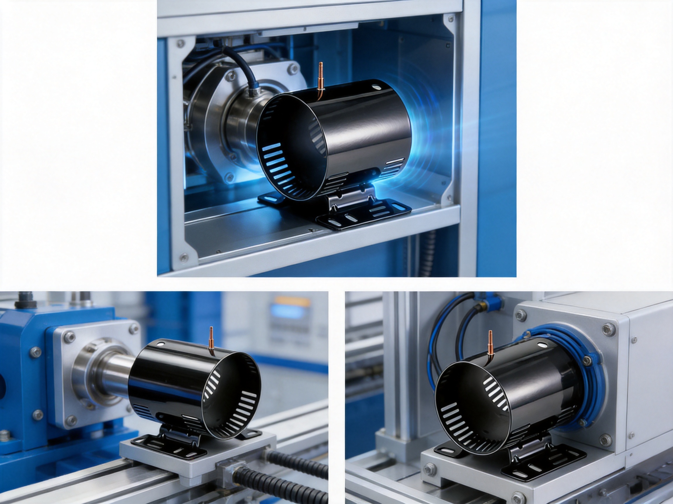
Before integrating the housing into a motor assembly, customers should verify the dimensional relationship among the housing, stator, rotor, end covers, bearings, shaft, mounting frame, and cable or grounding connections. The nominal inner diameter is listed as 96 mm, but the applicable tolerance must be confirmed from the approved drawing.
The stator insertion method should be selected according to the design. A clearance fit, transition fit, interference fit, adhesive-assisted assembly, or other method may be appropriate depending on the motor structure. The housing surface condition and roundness should be compatible with the selected assembly method.
The welded screw should be checked for position, thread condition, torque capability, and electrical contact requirements. If it is used for grounding, the finished motor should be tested according to the applicable electrical safety standard. Surface coatings must not interfere with the required conductive path unless an approved contact preparation method is used.
The mounting foot should be installed against a properly prepared support surface. Uneven mounting or excessive tightening force can distort the housing and affect internal alignment. Customers should define suitable fasteners, torque values, washers, and support conditions based on the final application.
Because motor vibration depends on the complete assembly, the housing should be evaluated together with the stator, rotor, bearings, end covers, and mounting structure. A precise housing cannot compensate for imbalance, bearing misalignment, loose fasteners, or an unsuitable installation frame elsewhere in the motor system.
Recommended Validation Program
A validation program helps confirm that the housing meets both dimensional and functional requirements. The exact program should be adapted to the customer’s industry and risk level, but several evaluation categories are generally useful.
Dimensional Validation
Measure the inner diameter, outer diameter, height, wall thickness, roundness, straightness, mounting-foot position, and welded-screw location. Measurements should be taken from representative samples across a production batch rather than from one sample only.
Assembly Validation
Install the housing with the intended stator and associated motor components. Check insertion force, fit, concentricity, clearance, end-cover compatibility, and mounting alignment. Confirm that the welded features do not interfere with internal or external components.
Mechanical Testing
Evaluate the mounting foot and welded screw under the expected loads. Testing may include static load, torque, vibration, shock, repeated loading, and fastener retention. The test conditions should reflect the actual application and include suitable safety margins.
Thermal Testing
Operate the motor under representative load and duty-cycle conditions. Record housing temperature, internal temperature where possible, temperature rise, cooling behavior, and heat distribution. Compare results with the previous housing design or customer-defined limits.
Noise and Vibration Testing
Measure vibration and acoustic behavior using the complete motor assembly. The housing’s dimensional accuracy and structural integrity can influence noise, but the final result also depends on rotor balance, bearing quality, electromagnetic forces, and mounting conditions.
Environmental Testing
Where required, test the housing and complete motor under humidity, temperature cycling, corrosion exposure, dust, chemical contact, or other environmental conditions. Surface treatment and material selection should be verified against the actual operating environment.
Customization Possibilities
The supplied product provides a defined reference configuration, but motor housing programs frequently require customization. Possible modifications may include changes to inner diameter, outer diameter, height, wall thickness, mounting-foot geometry, screw type, attachment position, openings, surface treatment, or packaging.
Customization should begin with a complete technical specification. Important information includes the motor application, operating temperature, expected load, vibration level, assembly process, electrical requirements, corrosion environment, annual volume, and applicable standards. These details help the manufacturer recommend a practical combination of material, forming method, welding process, and finish.
Changes to wall thickness may influence weight, heat transfer, stiffness, welding behavior, and tooling cost. Changes to the diameter may affect stator fit and rotor air gap. Changes to the mounting foot may alter load distribution and vibration behavior. For these reasons, even seemingly small modifications should be reviewed through engineering analysis and sample validation.
The manufacturer’s in-house capabilities can simplify customization because design changes can be evaluated across forming, welding, machining, and finishing operations. This integrated approach reduces the risk that a design is technically acceptable in one process but difficult or unstable in another.
Commercial Value for Motor Manufacturers
The commercial value of a motor housing should be evaluated through total cost rather than unit price alone. The Inner Diameter 95 Steel Motor Housing can contribute to total cost reduction by simplifying assembly, reducing secondary operations, limiting the number of separate mounting parts, and supporting repeatable production.
A welded screw may reduce the need for a drilling and tapping station. A welded mounting foot may remove the need for a separate bracket. A thin wall may reduce material use and handling weight. A stable supply chain may reduce production interruptions. When these benefits are calculated across thousands or millions of units, the impact can be more significant than a small difference in purchase price.
Integrated production can also reduce coordination costs. Instead of managing separate suppliers for formed bodies, welded attachments, machining, and surface treatment, the customer can work with one manufacturer for a broader portion of the process. This may simplify quality communication, corrective actions, production planning, and engineering changes.
The product is therefore well suited to customers that value a combination of compact design, functional integration, production scalability, and technical support. Its advantages are strongest when the housing is considered as part of the complete motor manufacturing system rather than as an isolated steel cylinder.
Frequently Asked Questions
What is the actual inner diameter of the product?
The supplied specification table lists an inner diameter of 96 mm. The commercial title refers to an inner diameter of 95, so customers should confirm the approved drawing, tolerance, and final production reference before ordering. The product code associated with the description is ID096002.
What are the main dimensions?
The listed dimensions are a 96 mm inner diameter, 99 mm outer diameter, 113 mm height, and 1.5 mm wall thickness. These are nominal values unless otherwise stated in the final technical drawing.
Which materials can be used?
The listed material specifications are SPCC, ST12, and DC01. The final grade should be selected according to forming requirements, mechanical performance, surface condition, welding needs, applicable standards, and customer documentation requirements.
Does the housing include a mounting feature?
Yes. A mounting foot is welded onto the housing. It provides a stable support point and can simplify positioning and installation in compact equipment.
Is a screw included in the housing design?
Yes. A screw is welded onto the housing. This can eliminate additional drilling or tapping in the corresponding assembly area and may support mechanical or electrical connection functions, subject to final application validation.
Why is the wall thickness only 1.5 mm?
The thin wall is intended to reduce weight, conserve material, maintain a compact external envelope, and support rapid heat conduction from the motor assembly to the outside surface. The forming and welding process must be carefully controlled to preserve dimensional accuracy and structural integrity.
Can the housing be customized?
Customization may be possible for dimensions, mounting features, welded attachments, openings, surface treatment, and other requirements. Customers should provide drawings or application information so the manufacturer can assess tooling, forming, welding, inspection, and validation needs.
Is this housing suitable for continuous motor operation?
The product description states that the housing is designed to support continuous motor operation through its thin-wall heat-transfer characteristics and firm welded construction. Final suitability must be confirmed through thermal, vibration, mechanical, and environmental testing of the complete motor assembly.
How does the product help reduce vibration and noise?
The optimized diameter-to-height relationship supports stable stator mounting and concentric alignment. Consistent housing geometry can help reduce misalignment-related vibration and noise. However, final motor noise also depends on rotor balance, bearings, electromagnetic design, assembly accuracy, and the external mounting structure.
What manufacturing processes are available?
The manufacturer provides integrated stamping, welding assembly, machining, surface treatment, inspection, and finished-product delivery. This supports coordinated production from steel processing through final component preparation.
What industries can use this type of motor housing?
Potential industries include household appliances, industrial drives, new energy vehicle-related equipment, automation systems, special machinery, and other compact motor applications. Each application requires its own performance and compliance validation.
What information should be confirmed before an order?
Customers should confirm the final drawing, dimensional tolerances, material grade, surface treatment, weld requirements, screw specification, mounting-foot geometry, annual volume, inspection standard, packaging method, and delivery schedule. If the housing is used for grounding or another electrical function, the applicable electrical requirements should also be specified.
Conclusion
The Inner Diameter 95 Steel Motor Housing is a compact steel enclosure designed to support reliable motor construction, efficient assembly, and stable long-term operation. Its listed 96 mm inner diameter, 99 mm outer diameter, 113 mm height, and 1.5 mm wall thickness create a practical balance between compactness, weight, thermal response, and structural support.
The product’s welded screw and welded mounting foot provide clear advantages over housings that require separate drilling, tapping, brackets, or extensive secondary assembly. These integrated features can reduce process steps, simplify installation, improve feature repeatability, and support mechanical or electrical connection requirements.
Its performance is supported by an integrated manufacturing system covering stamping, welding, machining, surface treatment, assembly, and inspection. The manufacturer’s decades of experience, engineering resources, customer base, and reported annual capacity provide a foundation for both customized development and volume production.
For motor manufacturers, the most important benefit is the combination of precision, functional integration, and production practicality. With appropriate drawing confirmation and application-specific validation, this housing can serve as a dependable component for compact motors used in appliances, industrial drives, new energy equipment, and specialized machinery.
References
1. Supplied product specification for Inner Diameter 95 Steel Motor Housing, product reference ID096002.
2. Supplied material information identifying SPCC, ST12, and DC01 steel specifications.
3. Supplied company information regarding stamping, welding, machining, assembly, surface treatment, inspection, engineering support, and production capacity.
4. General engineering principles for electric motor housing design, stator support, thermal transfer, vibration control, and dimensional inspection.
5. General manufacturing principles for cold-rolled steel forming, thin-wall fabrication, welded attachment design, and process quality control.

 Previous