

 English
 Español
Content
- 1 Product Overview
- 2 Structural Design and Mechanical Function
- 3 Ventilation and Thermal Management
- 4 Material Selection: SPCC, ST12, and DC01
- 5 Manufacturing Process and Quality Control
- 6 Advantages Compared with Conventional Motor Housing Options
- 7 Application Areas
- 8 Engineering and Customization Support
- 9 Company Manufacturing Strengths
- 10 Installation and Maintenance Considerations
- 11 Purchasing and Technical Evaluation Guide
- 12 Why This Housing Is a Practical Choice
- 13 Questions and Answers
- 13.1 What is the inner diameter of this steel motor housing?
- 13.2 What are the outer diameter and height?
- 13.3 What is the wall thickness?
- 13.4 Which materials can be used?
- 13.5 Why does the housing use three brackets instead of four?
- 13.6 What is the bracket bolt hole center distance?
- 13.7 How does the ventilation design help motor operation?
- 13.8 Can the housing be used in dusty or humid environments?
- 13.9 Is customization available?
- 13.10 What manufacturing processes does the supplier provide?
- 13.11 What industries can use this product?
- 13.12 What should be confirmed before placing an order?
- 14 Conclusion
- 15 References
- 16 Product: Inner Diameter 140 Steel Motor Housing With Three Brackets
Reliable motor performance depends on more than the electrical design of the stator, rotor, and winding system. The mechanical housing also plays a central role in protecting internal components, controlling heat, maintaining alignment, resisting vibration, and simplifying installation. For medium-to-small power motors used in industrial, agricultural, commercial, and specialized equipment, a well-designed steel housing can improve operating stability while supporting efficient and economical production.
The Inner Diameter 140 Steel Motor Housing with Three Brackets is engineered for applications that require a compact structure, effective heat dissipation, stable mounting, and consistent dimensional performance. With an inner diameter of 139.3 mm, an outer diameter of 142.3 mm, a height of 114.3 mm, and a wall thickness of 1.5 mm, this housing provides a practical balance between internal clearance, structural strength, material efficiency, and overall weight.
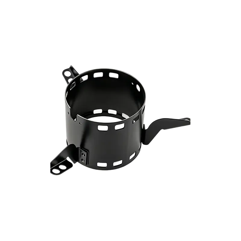
Manufactured from SPCC, ST12, or DC01-grade steel, the housing is suitable for a wide range of motor assemblies and equipment configurations. Its welded three-bracket mounting system creates a stable three-point support arrangement, while ventilation holes at both ends help establish an axial airflow path through the housing. These features make the product particularly suitable for industrial fans, exhaust equipment, agricultural machinery, food processing machines, packaging systems, and other equipment operating in compact spaces or under demanding thermal conditions.
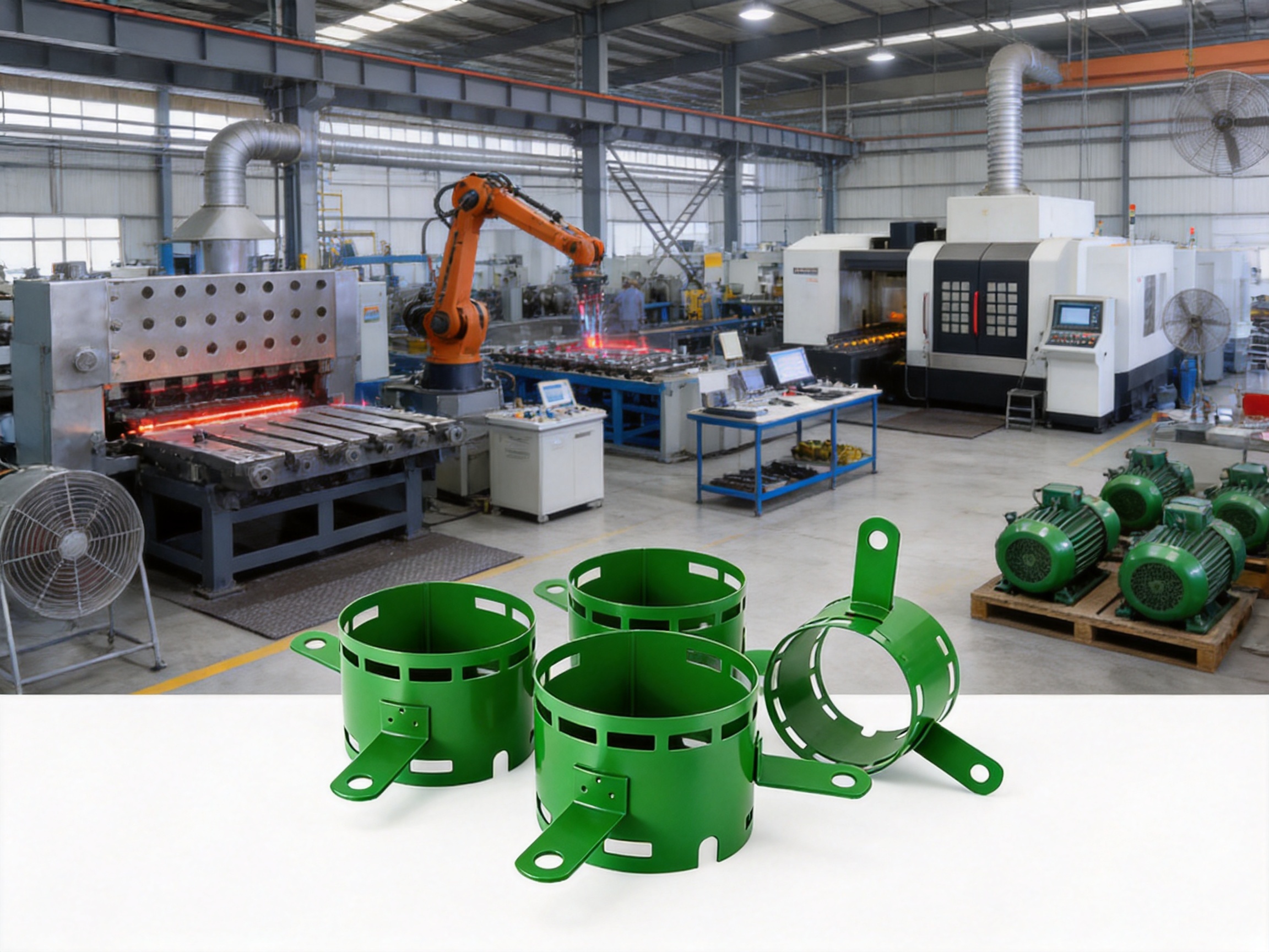
Jiangsu Yufeng Electric Co., Ltd. supports the production of this motor housing through an integrated manufacturing system that includes stamping, welding, machining, assembly, surface treatment, and inspection. This full-process capability allows the manufacturer to manage quality and dimensional consistency across multiple production stages, from raw steel processing to finished product delivery.
Product Overview
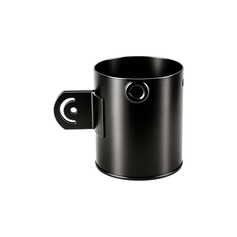
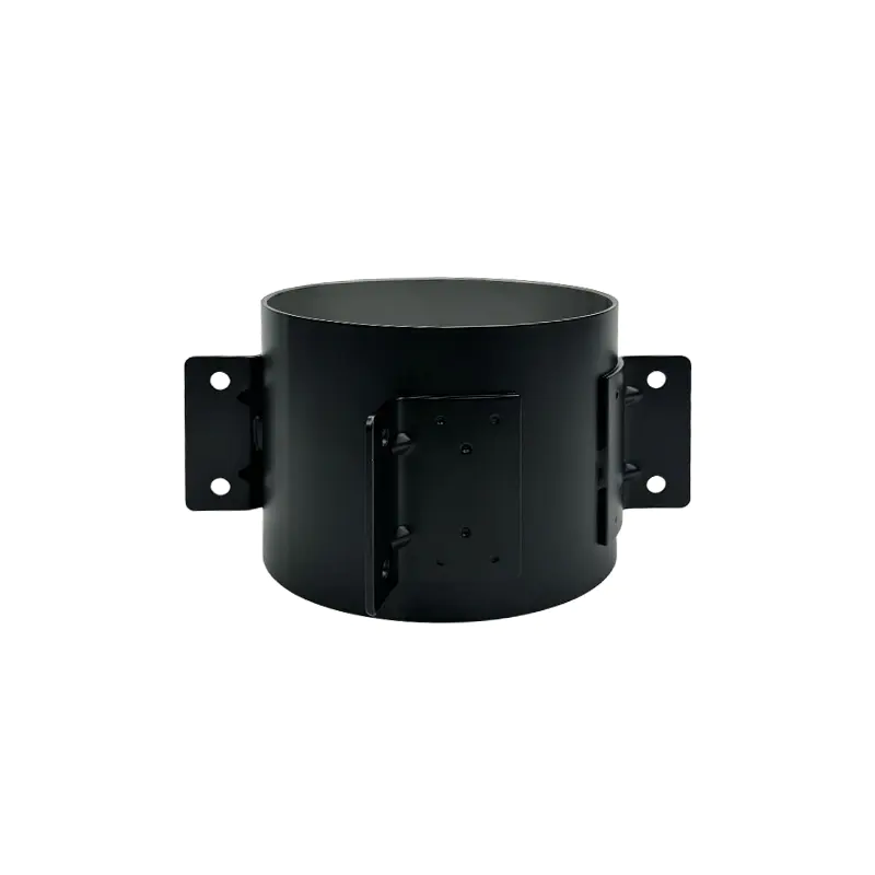
The Inner Diameter 140 Steel Motor Housing with Three Brackets is a cylindrical steel enclosure designed to accommodate a motor stator and associated internal components. Its primary function is to provide a rigid external structure that protects the motor interior while supporting heat dissipation and mechanical installation.
The housing has an inner diameter of 139.3 mm. This dimension is important because it determines the available internal space for the stator assembly and influences the relationship between the stator, rotor, insulation system, and other motor components. A controlled inner diameter helps motor manufacturers maintain predictable assembly clearances and reduce the risk of interference during production or operation.
The outer diameter is 142.3 mm, resulting from the 1.5 mm wall thickness. This relatively thin but sufficiently robust wall design supports lightweight construction without abandoning the mechanical advantages of steel. For many medium-to-small power motor applications, excessive housing thickness can increase material consumption, weight, and manufacturing cost without producing a corresponding performance benefit. The specified wall thickness is therefore intended to provide an efficient balance between rigidity and economy.
The total housing height is 114.3 mm. This compact axial dimension allows the part to be integrated into equipment with limited installation space. It can be useful in machinery where the motor must fit inside a narrow fan body, compact drive module, agricultural mechanism, or packaging machine enclosure.
Three welded mounting feet are positioned on the bottom of the housing. The bolt hole center distance between the brackets is 280 mm, providing a defined installation geometry for equipment designers and assembly technicians. The brackets are not merely accessories; they are an integral part of the housing’s mounting and vibration-management system.
| Specification | Value | Engineering Significance |
|---|---|---|
| Product type | Steel motor housing with three brackets | Combines motor protection, support, and installation functions |
| Inner diameter | 139.3 mm | Defines the available stator installation space |
| Nominal product class | Inner Diameter 140 | Provides a convenient reference for motor matching |
| Outer diameter | 142.3 mm | Reflects the 1.5 mm wall thickness |
| Height | 114.3 mm | Supports compact axial installation |
| Wall thickness | 1.5 mm | Balances weight, stiffness, and steel consumption |
| Material specification | SPCC / ST12 / DC01 | Provides cold-rolled steel options for forming and fabrication |
| Bracket bolt hole center distance | 280 mm | Defines the mounting interface |
| Mounting configuration | Three welded brackets | Provides three-point support and vibration resistance |
Structural Design and Mechanical Function
A motor housing must perform several functions simultaneously. It must hold the stator securely, maintain a stable circular geometry, protect the motor from external contact, transfer or release heat, and connect the motor assembly to the surrounding machine. The design of this product addresses each of these requirements through a combination of cylindrical steel construction, controlled dimensions, end ventilation, and welded supports.
Cylindrical Steel Body
The cylindrical body provides a continuous enclosure around the motor’s active components. Compared with an open frame or a loosely supported sheet-metal cover, a closed cylindrical housing can offer more uniform support around the stator. The continuous wall also helps protect the motor from accidental impact, dust generated during nearby operations, and mechanical contact with adjacent equipment.
The cylindrical form is efficient from a manufacturing perspective. A circular housing can be produced through controlled forming and stamping operations, then processed through welding, machining, and finishing stages as needed. This creates a repeatable production route that is suitable for both prototype development and larger-volume orders.
Dimensional consistency is particularly important in circular motor housings. Variations in roundness, diameter, or axial alignment may influence stator insertion, rotor clearance, bearing alignment, and overall motor noise. Integrated production and inspection capabilities help reduce these risks by allowing the manufacturer to control the part through multiple processing stages rather than relying entirely on external suppliers.
1.5 mm Wall Thickness
The 1.5 mm wall thickness represents a practical lightweight design choice. Steel offers greater rigidity and impact resistance than many thin nonmetallic alternatives, but using excessive steel can make the motor heavier and more difficult to install. A controlled wall thickness helps reduce unnecessary material usage while preserving the structural foundation required for a compact motor.
For equipment manufacturers, a lighter housing can provide several benefits. It may reduce the load placed on a supporting frame, simplify manual handling during assembly, and contribute to lower total equipment weight. In mobile agricultural equipment, fan systems, and compact machinery, every reduction in unnecessary mass can improve design flexibility.
At the same time, wall thickness must be evaluated together with the final application. Motor speed, vibration level, mounting arrangement, operating temperature, environmental exposure, and expected service life all affect the suitability of a housing. The 1.5 mm design is intended for compatible medium-to-small power applications where the selected material and support arrangement provide sufficient strength for the operating conditions.
Three-Point Mounting Arrangement
The three welded brackets form one of the most distinctive features of this product. A three-point support arrangement establishes a stable mounting plane without requiring all support points to be perfectly coplanar. In practical installation conditions, three points can define a plane more naturally than four points, which may be affected by small dimensional differences or uneven mounting surfaces.
Compared with a four-foot configuration, three-point support can be easier to level during equipment assembly. If four support points are not aligned precisely, one point may carry less load or create local stress when bolts are tightened. A three-point arrangement can reduce this type of installation difficulty, provided that the equipment frame and bolt layout are designed appropriately.
The three brackets also help distribute mechanical loads around the lower part of the housing. During operation, the motor may experience vibration caused by rotor imbalance, fan loading, electromagnetic forces, or changes in the connected equipment. A properly welded bracket system helps transfer these forces to the equipment frame while maintaining a secure connection.
The 280 mm bracket bolt hole center distance provides a clear reference for equipment designers. It enables the motor housing to be incorporated into a defined mounting layout and helps reduce uncertainty when preparing assembly drawings, jigs, and support frames.
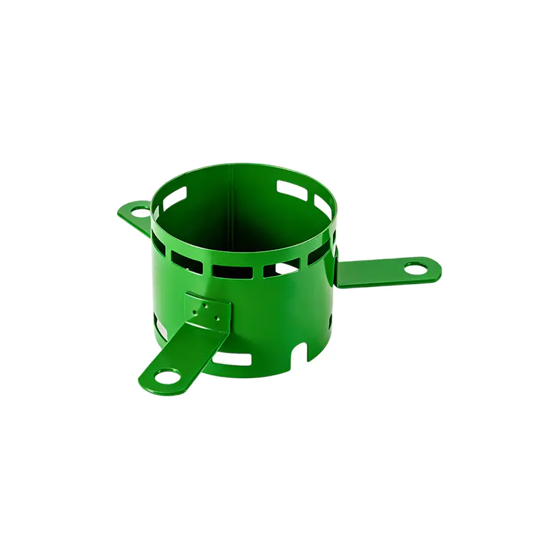
Inner Diameter 140 Steel Motor Housing With Three Brackets
Ventilation and Thermal Management
Heat management is one of the most important considerations in motor housing design. Electrical resistance, magnetic losses, friction, and mechanical loading all generate heat during motor operation. If this heat remains trapped around the stator and rotor, the temperature of the windings, insulation, bearings, and surrounding components may rise beyond desirable operating levels.
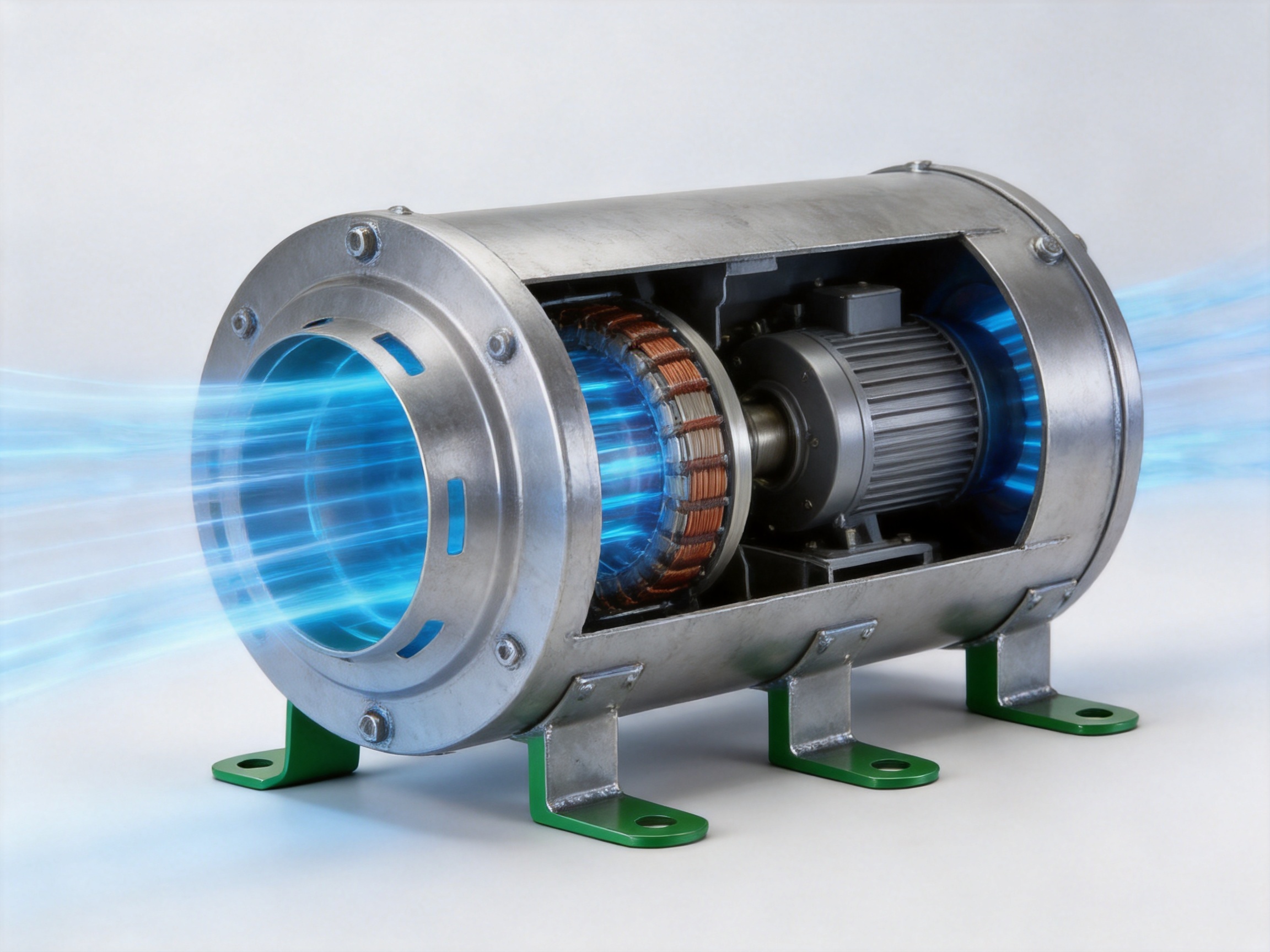
This housing includes ventilation holes at both ends. When integrated into a suitable motor assembly, these openings can establish an axial air cooling channel. Air can enter through one end, pass through the interior region, absorb or carry away heat, and exit through the opposite end. The actual airflow rate depends on the motor’s fan structure, rotational speed, equipment layout, ambient temperature, and the design of the surrounding enclosure.
Axial Airflow Path
The axial ventilation concept is straightforward but effective. Instead of allowing hot air to remain concentrated near the stator, the housing provides a path for air movement along the length of the motor. This can help reduce local heat accumulation and promote a more uniform temperature distribution.
For compact motors, the available surface area for heat dissipation may be limited. A ventilation channel can therefore complement heat transfer through the steel wall. The steel body helps conduct heat toward the external surface, while air movement through the housing helps carry heat away from internal regions.
Improved thermal conditions can support longer periods of continuous operation. Lower temperature rise may help protect winding insulation and reduce thermal stress on internal components. It can also contribute to more stable performance when the motor is installed in equipment that operates for extended periods.
Ventilation openings must always be considered alongside the application environment. In food processing, agricultural, or dusty industrial environments, the motor assembly may require suitable filters, guards, seals, or cleaning procedures. The housing provides a ventilation structure, but the final equipment designer remains responsible for ensuring that airflow and environmental protection requirements are balanced correctly.
Thermal Benefits for Compact Equipment
Compact machinery often presents a difficult thermal design challenge. There may be limited space around the motor, restricted external airflow, or nearby components that are sensitive to heat. A housing with an integrated axial airflow concept can help equipment designers use the available space more effectively.
Industrial fans and exhaust systems are examples of applications where airflow and motor operation are closely connected. The motor must operate reliably while driving a rotating fan, and heat generated by the motor can affect the surrounding assembly. A ventilated housing can support the overall cooling strategy without requiring a much larger external enclosure.
Packaging machinery may also benefit from a compact, ventilated motor housing. Such equipment frequently combines motors, conveyors, rollers, sensors, and control systems within a limited footprint. A housing that contributes to heat removal can help reduce the likelihood of heat accumulation around neighboring components.
Material Selection: SPCC, ST12, and DC01
The listed material specifications are SPCC, ST12, and DC01. These designations generally refer to cold-rolled low-carbon steel grades used in sheet-metal forming and fabrication. The exact mechanical and surface requirements should be confirmed according to the purchasing specification, applicable standards, and intended finishing process.
Cold-rolled steel is widely used in motor housing production because it offers a controlled surface, consistent thickness, good formability, and suitability for stamping and welding. These characteristics are valuable when producing cylindrical bodies and welded brackets that require repeatable geometry.
Formability
Motor housings often require forming operations that transform flat steel sheet into a precise cylindrical or shaped component. Good formability helps reduce cracking, excessive springback, and dimensional variation during production. It also supports efficient manufacturing of repeated parts.
For high-volume applications, material behavior must remain consistent from batch to batch. Variations in thickness, hardness, or surface condition can influence forming force, tool wear, weld quality, and final dimensions. A manufacturer with established material control procedures can better manage these variables.
Weldability
The housing includes three welded mounting feet, so weldability is an essential material consideration. Consistent low-carbon steel can support stable welding conditions and help produce joints with sufficient mechanical integrity. Welding parameters must be selected according to material thickness, bracket geometry, joint design, and required production speed.
Weld quality affects more than appearance. Poorly controlled welding may result in incomplete fusion, excessive spatter, distortion, or local weakness. Distortion can also affect the position of the mounting holes and the relationship between the brackets and the cylindrical body. Automated or controlled welding equipment, combined with inspection, helps minimize these risks.
Surface and Finishing Compatibility
Cold-rolled steel provides a suitable foundation for subsequent surface treatment. Depending on the customer’s application, finishing may include cleaning, coating, painting, plating, or another corrosion-control process. The appropriate finish depends on humidity, chemical exposure, outdoor use, food-processing requirements, appearance expectations, and cost targets.
Surface treatment can also improve the service life of the housing by helping protect the steel from oxidation. The final treatment should be selected together with the operating environment rather than treated as a separate cosmetic decision.
Manufacturing Process and Quality Control
The performance of a motor housing is closely related to the stability of its manufacturing process. A good design can lose its intended advantages if forming, welding, machining, or inspection is inconsistent. Jiangsu Yufeng Electric Co., Ltd. provides an integrated production capability covering stamping, welding assembly, machining, surface treatment, and inspection.
This integrated approach allows key production steps to be coordinated under one manufacturing system. It can reduce communication gaps between process departments, improve traceability, and support faster adjustments when a customer requires a dimensional or structural modification.
Stamping and Sheet-Metal Forming
Stamping is an important process for efficiently producing steel components with repeatable dimensions. Properly designed dies can help control the shape of the housing body, end features, ventilation openings, and other formed elements. Production tooling can be developed according to the housing’s geometry, material thickness, and required volume.
During stamping, process control may include monitoring material positioning, press parameters, die condition, part geometry, and surface quality. Consistent control helps reduce burrs, deformation, scratches, and dimensional variation.
For customer programs involving recurring production, stable stamping performance is especially valuable. It allows motor manufacturers to receive housings with predictable dimensions and reduces the need for repeated manual correction during assembly.
Welding Assembly
After forming, the mounting brackets can be positioned and welded to the housing body. The three-foot design requires accurate control of bracket location, orientation, and bolt hole spacing. Welding fixtures can help hold the components in the correct relationship during joining.
Fixture design is important because heat input during welding can create distortion. A suitable fixture supports the housing and brackets while maintaining the required geometry. Welding sequence, current, travel speed, and clamping method may all influence the final result.
After welding, the brackets can be checked for location, alignment, visible defects, and mechanical stability. The bolt hole center distance of 280 mm should be verified as part of the dimensional inspection program when that dimension is critical to the customer’s assembly.
Machining and Dimensional Refinement
Some motor housing applications require machining after forming and welding. Machining may be used to refine mounting surfaces, holes, end faces, or other interfaces that require tighter dimensional control. The exact operations depend on the customer’s drawing and the motor assembly design.
Machining can improve the consistency of critical interfaces, but it must be planned carefully to avoid removing excessive material or weakening a thin-wall structure. A coordinated manufacturing process allows the machining route to be selected based on the stamped and welded condition of the part.
Surface Treatment
Surface treatment helps prepare the housing for its working environment. It may improve corrosion resistance, appearance, cleanability, or compatibility with the final equipment. The treatment process can be selected according to the customer’s technical requirements and the intended operating conditions.
For equipment used in humid or chemically active environments, corrosion protection may be especially important. For food processing machinery, the finish should be evaluated for cleanability and suitability for the surrounding hygiene regime. In agricultural equipment, the treatment may need to withstand moisture, dust, and outdoor exposure.
Inspection and Testing
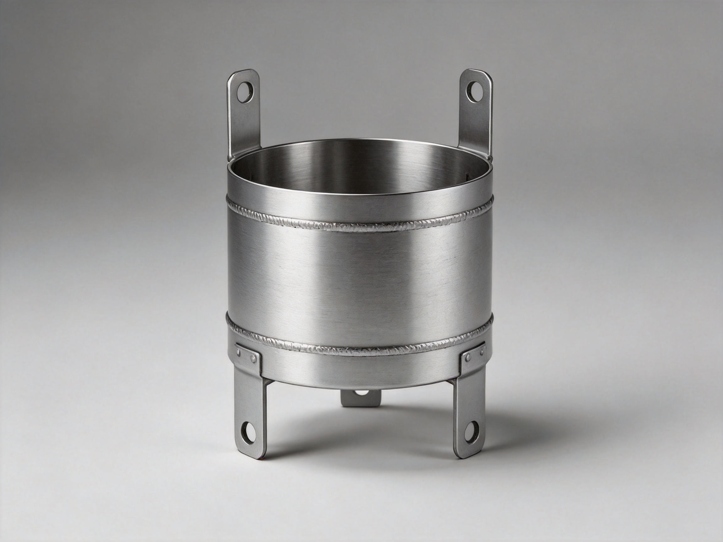
Inspection is essential for confirming that the product matches the required dimensions and assembly interface. Typical checks may include inner diameter, outer diameter, height, wall thickness, bracket spacing, hole position, weld appearance, and overall deformation.
Inspection instruments can also support process verification and production traceability. When inspection data is reviewed over time, manufacturers can identify trends such as gradual tool wear, fixture movement, or changes in forming behavior before these issues create larger production problems.
The manufacturer’s inspection capabilities support its objective of delivering high-precision and high-reliability motor housing solutions. Customer-specific inspection plans can be established when a project involves critical tolerances, special materials, or demanding assembly requirements.
Advantages Compared with Conventional Motor Housing Options
Motor housings are available in many configurations, including cast housings, extruded aluminum bodies, four-foot steel housings, open frames, and various welded enclosures. The best selection depends on the application. The Inner Diameter 140 Steel Motor Housing with Three Brackets offers several advantages in situations where steel strength, compact ventilation, and stable three-point mounting are priorities.
Advantage One: Balanced Strength and Lightweight Construction
Compared with a heavily built steel housing, the 1.5 mm wall design can reduce material use and overall mass. At the same time, steel retains useful rigidity and impact resistance for many industrial applications. This balance can make the housing easier to handle during assembly while maintaining a dependable external structure around the motor.
Compared with some lightweight alternatives, steel may offer a more economical solution where robust protection and welded mounting are required. It can also be attractive when the customer’s existing production system is already configured for steel stamping and welding.
Advantage Two: Three-Point Installation Stability
The three welded brackets provide a practical alternative to four-point mounting. Three points can simplify leveling and reduce sensitivity to minor variations in the supporting frame. This feature may be especially useful in equipment where installation access is limited or where assembly speed is important.
A three-point design can also reduce bracket material and simplify the overall support structure. Fewer mounting feet may contribute to lower weight and fewer potential points of misalignment, while still providing stable support when the equipment frame is properly designed.
Advantage Three: Integrated Ventilation
Ventilation holes at both ends help establish an axial air passage through the motor housing. Compared with a fully closed housing, this design provides a clearer route for internal airflow. Compared with an open frame, it still provides a more complete protective enclosure around the motor components.
This balance between protection and ventilation is valuable in machinery that requires cooling but also needs a defined housing around the motor. The final cooling performance will depend on the complete motor and equipment design, but the housing provides a useful structural foundation for thermal management.
Advantage Four: Adaptability to Compact Equipment
The 114.3 mm height and 142.3 mm outer diameter support compact integration. Equipment designers can use the defined dimensions to plan the motor compartment, bracket frame, guards, and airflow path. This can be advantageous where the motor must fit within a restricted installation envelope.
The product’s application range includes industrial fans, exhaust equipment, agricultural machinery motors, food processing equipment, packaging machinery, and other medium-to-small power equipment. These applications commonly require a combination of compact dimensions, reliable support, and effective heat management.
Advantage Five: Integrated Manufacturing Support
A supplier capable of stamping, welding, machining, assembly, surface treatment, and inspection can provide more than a basic metal component. Such a supplier can participate in design review, process development, sample production, tolerance evaluation, and volume manufacturing.
This integrated capability can reduce the number of external interfaces in a project. It may also make it easier to respond to design changes, adjust tooling, coordinate finishing requirements, and manage quality documentation.
Application Areas
Industrial Fans and Exhaust Equipment
Industrial fans and exhaust systems often operate for long periods and may be installed in spaces where airflow and heat management are important. The ventilated housing can support axial air movement through the motor assembly, while the three brackets provide a stable method of securing the motor to the equipment frame.
In exhaust equipment, the motor may be exposed to vibration generated by the fan wheel and airflow resistance. A stable housing and properly designed mounting frame can help maintain alignment and reduce the risk of loosened fasteners or excessive structural movement.
Agricultural Machinery
Agricultural machinery may operate in dusty, humid, and mechanically demanding environments. Motors used in ventilation systems, feed processing equipment, pumps, conveyors, and other agricultural machines require dependable mechanical support and appropriate environmental protection.
The steel construction offers a practical foundation for protective finishing, while the compact dimensions can simplify integration into machinery with limited space. The final product selection should consider dust protection, cleaning methods, corrosion exposure, and the need for guards or filters around ventilation openings.
Food Processing Equipment
Food processing machinery often requires compact, cleanable, and dependable motor components. Motors may be used in conveyors, mixers, packaging lines, cutting systems, exhaust units, and auxiliary equipment. A steel housing with a suitable surface treatment can be integrated into equipment designed for regular cleaning and maintenance.
When used in a food-related environment, the housing finish, weld condition, exposed edges, cleaning chemicals, and ventilation arrangement should all be evaluated. The housing can be customized or finished according to the specific hygiene and corrosion requirements of the application.
Packaging Machinery
Packaging machinery frequently contains multiple motors in a compact arrangement. Space efficiency, repeatable installation, low maintenance, and stable operation are important considerations. The Inner Diameter 140 housing can support compact motor packages while providing a defined bracket interface and ventilation path.
Its three-point mounting arrangement may also simplify the installation of motors on machine frames that are difficult to access. With a clear bolt hole center distance, equipment builders can prepare standardized mounting plates and assembly fixtures.
General Medium-to-Small Power Equipment
The product is suitable for other equipment requiring a steel motor enclosure with compact dimensions and stable support. Possible applications include auxiliary drives, small ventilation units, specialized machinery, and equipment modules where a custom motor housing is required.
Because motor requirements vary widely, application approval should be based on the customer’s drawings, load conditions, speed, temperature, vibration, environmental exposure, and assembly method. The product’s defined dimensions provide a strong starting point for technical evaluation.
Engineering and Customization Support
Motor housing projects often begin with a customer drawing, a motor sample, a dimensional requirement, or a performance target. A capable manufacturer should be able to convert this information into a practical production process. Jiangsu Yufeng Electric Co., Ltd. offers engineering support from product development through mass production.
Engineering review may include evaluation of material selection, wall thickness, forming method, bracket geometry, ventilation openings, weld sequence, machining requirements, and surface treatment. This review helps identify potential manufacturing risks before tooling or mass production begins.
Design for Manufacturing
Design for manufacturing is particularly important for thin-wall steel housings. Features that are easy to represent in a drawing may be difficult to stamp, weld, or inspect consistently. Early review can help identify sharp transitions, inaccessible weld locations, unnecessary tolerances, and features that may increase cost without improving function.
The goal is not simply to produce the first sample. The objective is to create a stable process that can deliver consistent parts over the full production quantity. This is especially important for motor manufacturers that need repeatable assembly performance across thousands or millions of units.
Prototype and Sample Development
Before mass production, customers may require samples for dimensional inspection, motor assembly trials, thermal testing, vibration testing, or equipment integration. A structured sample-development process can help confirm that the housing meets the intended interface and performance requirements.
Feedback from the sample stage can be used to adjust bracket position, hole spacing, ventilation size, surface treatment, or other details. Close coordination between the customer and manufacturer can reduce the time required to move from concept to production.
Mass Production Capability
Jiangsu Yufeng Electric has an annual production capacity of over 5 million units and has served more than 50 customers. This experience supports the requirements of customers seeking a supplier for recurring motor housing programs.
Mass production requires more than high equipment capacity. It also requires process discipline, material planning, tooling maintenance, inspection routines, production scheduling, and delivery coordination. The company’s full-process manufacturing model is designed to support these requirements from steel processing through finished product delivery.
Company Manufacturing Strengths
Jiangsu Yufeng Electric Co., Ltd. is a professional manufacturer specializing in the research, development, and production of motor housings. Its capabilities include stamping, welding assembly, machining, surface treatment, and inspection. This combination enables the company to manage a broad range of motor housing requirements within one coordinated production system.
The company has approximately 40 years of experience in motor housing manufacturing. Its engineering team has an average of more than 20 years of experience, providing technical support during product development, process planning, troubleshooting, and mass production.
Full-Process Production
Full in-house production can help improve communication between design, manufacturing, and quality departments. When a customer requests a modification, the supplier can evaluate the impact across stamping, welding, machining, and finishing operations rather than addressing only one isolated process.
This approach may also improve delivery coordination. Fewer external process transfers can reduce transportation between facilities, simplify scheduling, and provide a clearer view of production status. For customers managing multiple motor programs, consolidated manufacturing can make supplier coordination more efficient.
Engineering Experience
Motor housings must meet both mechanical and manufacturing requirements. The engineering team’s experience can help customers evaluate the relationship between the housing and the stator, rotor, bearings, motor frame, fan structure, and installation system.
Experienced engineers can also help identify the practical implications of a requested tolerance or design feature. For example, a tight dimensional requirement may require additional machining, a specialized fixture, or a revised forming route. Reviewing these factors early can help customers make informed decisions about performance and cost.
Quality and Responsiveness
The company is guided by quality, efficiency, and fast response. These priorities are relevant to customers that require both reliable parts and prompt technical communication. A responsive supplier can provide faster feedback on drawings, samples, production questions, and corrective actions.
Quality is supported through production equipment, automated welding capability, machining facilities, and inspection instruments. While specific inspection plans should be agreed with each customer, the available infrastructure provides a foundation for controlling dimensions and manufacturing consistency.
Installation and Maintenance Considerations
Correct installation is essential to obtaining the intended benefits of any motor housing. Before assembly, the customer should confirm that the motor components match the specified inner diameter, height, mounting arrangement, and ventilation requirements.
Mounting Surface Preparation
The equipment frame should provide an appropriate support surface for the three brackets. The mounting area must be sufficiently rigid and should match the 280 mm bracket bolt hole center distance. The frame should also allow adequate access for fasteners, tools, inspection, and future maintenance.
Because three-point mounting is intended to simplify leveling, installers should avoid forcing the housing into position through excessive bolt tightening. The housing should be seated naturally on the support points, and fasteners should be tightened in a controlled sequence.
Alignment
The motor shaft and connected equipment must be aligned according to the requirements of the complete assembly. Misalignment can create additional vibration, bearing load, noise, and wear. The housing supports the motor, but alignment also depends on the shaft, bearings, coupling, driven equipment, and frame.
Ventilation Clearance
Ventilation holes should not be blocked by nearby panels, insulation, cables, or structural members. Adequate clearance should be maintained to support airflow through the housing. If the application contains dust, fibers, oil mist, or moisture, suitable protective measures should be added without restricting cooling beyond acceptable limits.
Fastener and Weld Inspection
During routine maintenance, the mounting fasteners can be checked for loosening, corrosion, or damage. The welded bracket areas should also be examined for visible cracks, deformation, or unusual movement. Any change in vibration or noise should be investigated because it may indicate a problem with the motor, connected equipment, mounting frame, or housing interface.
Purchasing and Technical Evaluation Guide
When evaluating this motor housing for a new project, customers should compare the product dimensions with their motor design and equipment envelope. The inner diameter of 139.3 mm, outer diameter of 142.3 mm, height of 114.3 mm, and bracket spacing of 280 mm should be reviewed against the customer’s assembly drawings.
Material requirements should also be confirmed. SPCC, ST12, and DC01 may be specified according to the customer’s regional standards and procurement system. The required material grade, thickness tolerance, surface condition, and finish should be documented in the purchase specification.
Customers should identify whether the housing requires additional machining, special ventilation dimensions, customized bracket geometry, corrosion-resistant treatment, painting, marking, packaging, or inspection documentation. These requirements can be reviewed during the product-development stage.
Application conditions should include operating temperature, motor speed, vibration level, duty cycle, ambient humidity, dust exposure, cleaning chemicals, expected service life, and installation orientation. Providing this information helps the manufacturer evaluate whether the standard configuration is suitable or whether customization is required.
Why This Housing Is a Practical Choice
The Inner Diameter 140 Steel Motor Housing with Three Brackets combines several useful features in one compact component. Its 1.5 mm steel wall supports a balance between strength and weight. Its 139.3 mm internal diameter provides a defined space for the motor assembly. Its 114.3 mm height supports compact installation, while its 142.3 mm outer diameter provides a clear external envelope for equipment design.
The three welded mounting feet offer a stable and potentially easier-to-level support arrangement. The 280 mm bolt hole center distance provides a clear installation reference. Ventilation holes at both ends support an axial cooling path that can help manage internal heat when incorporated into a suitable motor system.
In comparison with less integrated or less application-specific housing options, this product provides a well-defined combination of mechanical support, thermal assistance, and manufacturing efficiency. Its value is further strengthened by the manufacturer’s ability to handle stamping, welding, machining, surface treatment, assembly, and inspection.
For customers seeking a reliable motor housing supplier, manufacturing capability is as important as the individual product design. A supplier with long-term experience, engineering support, production capacity, and integrated process control can provide greater continuity from initial drawing review to volume delivery.
Questions and Answers
What is the inner diameter of this steel motor housing?
The measured inner diameter specified for the housing is 139.3 mm. The product is classified as an Inner Diameter 140 steel motor housing for convenient product identification and motor matching.
What are the outer diameter and height?
The outer diameter is 142.3 mm, and the housing height is 114.3 mm. These dimensions should be checked against the customer’s motor assembly and available equipment space before ordering.
What is the wall thickness?
The wall thickness is 1.5 mm. This thickness is intended to balance structural support, weight reduction, and material efficiency for compatible medium-to-small power motor applications.
Which materials can be used?
The listed material specifications are SPCC, ST12, and DC01. The final grade should be confirmed according to the customer’s technical drawing, regional standard, surface requirements, and operating environment.
Why does the housing use three brackets instead of four?
A three-point support arrangement can simplify leveling and reduce sensitivity to small variations in the mounting frame. It may also reduce material usage and overall weight. The final equipment frame must be designed to match the three-bracket configuration.
What is the bracket bolt hole center distance?
The specified bracket bolt hole center distance is 280 mm. Customers should verify this dimension against their mounting plate, machine frame, and assembly tooling.
How does the ventilation design help motor operation?
Ventilation holes at both ends can establish an axial airflow channel through the housing. This airflow can help carry heat away from the stator and rotor region, reduce temperature rise, and support longer continuous operation when the complete motor and equipment design provides suitable airflow.
Can the housing be used in dusty or humid environments?
It may be used in suitable dusty or humid applications when the material, surface treatment, ventilation protection, and overall motor design are selected appropriately. Filters, guards, coatings, seals, or cleaning procedures may be required depending on the environment.
Is customization available?
Customization can be evaluated according to the customer’s drawings and application requirements. Potential areas include dimensions, bracket layout, ventilation features, machining, surface treatment, marking, packaging, and inspection requirements.
What manufacturing processes does the supplier provide?
The supplier provides stamping, welding assembly, machining, surface treatment, assembly, and inspection capabilities. This integrated production model supports development from steel processing through finished motor housing delivery.
What industries can use this product?
Potential applications include industrial fans, exhaust equipment, agricultural machinery, food processing equipment, packaging machinery, and other medium-to-small power equipment requiring compact installation, effective heat dissipation, and stable mounting.
What should be confirmed before placing an order?
Customers should confirm the inner diameter, outer diameter, height, wall thickness, material grade, bracket bolt hole center distance, ventilation requirements, surface treatment, operating environment, motor compatibility, required tolerances, quantity, packaging, and inspection documentation.
Conclusion
The Inner Diameter 140 Steel Motor Housing with Three Brackets is designed as a practical solution for motor applications requiring compact dimensions, stable installation, efficient airflow, and economical steel construction. Its 139.3 mm inner diameter, 142.3 mm outer diameter, 114.3 mm height, and 1.5 mm wall thickness provide a clearly defined mechanical envelope for equipment designers.
The three welded brackets create a stable three-point support system and may simplify leveling compared with four-point mounting arrangements. The 280 mm bolt hole center distance provides a clear installation reference, while ventilation holes at both ends support an axial cooling channel for compatible motor designs.
Its advantages are reinforced by the manufacturing capabilities of Jiangsu Yufeng Electric Co., Ltd. With experience in motor housing production, a skilled engineering team, full-process manufacturing, an annual production capacity exceeding 5 million units, and capabilities covering stamping, welding, machining, assembly, surface treatment, and inspection, the company can support both standard and customized motor housing programs.
For equipment manufacturers, motor producers, and engineering teams, this housing offers more than a steel enclosure. It provides a coordinated combination of mechanical protection, thermal assistance, installation stability, material efficiency, and manufacturing support. When its dimensions and material specifications are matched correctly to the application, it can serve as a reliable foundation for industrial fans, exhaust systems, agricultural machinery, food processing equipment, packaging machines, and other compact motor-driven equipment.
References
1. Product specification information for the Inner Diameter 140 Steel Motor Housing with Three Brackets, including dimensions, material specifications, and bracket spacing.
2. Jiangsu Yufeng Electric Co., Ltd. company manufacturing profile and motor housing production capabilities.
3. General engineering principles for steel sheet forming, welded motor housing fabrication, dimensional inspection, and surface treatment.
4. General motor design principles concerning ventilation, temperature rise, vibration control, mounting stability, and equipment integration.
5. General technical information regarding SPCC, ST12, and DC01 cold-rolled steel materials used in fabricated electrical and mechanical components.

 Previous