

 English
 Español
Content
- 1 Product Overview
- 2 Why the 1.0 mm Thin-Wall Structure Matters
- 3 Integrated End Covers and Structural Assembly
- 4 Welded Bearing Housings for Alignment Efficiency
- 5 Pre-Installed Welded Studs for Faster Mounting
- 6 Axial Ventilation and Thermal Management
- 7 Material Selection: SPCC, ST12, and DC01
- 8 Manufacturing Process and Production Integration
- 9 Quality Control for a Thin-Wall Motor Housing
- 10 Advantages Compared with Conventional Housing Solutions
- 11 Application Areas
- 12 Engineering and Customization Considerations
- 13 Benefits of Full In-House Production
- 14 Production Efficiency and Customer Value
- 15 Assembly Guidance and Handling
- 16 Testing and Validation
- 17 How the Product Supports Modern Compact Equipment
- 18 Frequently Asked Questions
- 18.1 What is the inner diameter of the housing?
- 18.2 What are the outer diameter and height?
- 18.3 What is the wall thickness?
- 18.4 What material is used?
- 18.5 Does the product include end covers?
- 18.6 Are bearing housings included?
- 18.7 How many mounting studs are provided?
- 18.8 Does the housing support motor cooling?
- 18.9 Can the housing be used for drone motors?
- 18.10 Is it suitable for portable power tools?
- 18.11 Can the housing be customized?
- 18.12 What manufacturing processes are available?
- 18.13 What should customers provide before requesting production?
- 18.14 Does the housing provide a completely sealed enclosure?
- 18.15 How should the housing be validated?
- 19 Conclusion
- 20 References
- 21 Product: Inner Diameter 82.4 Steel Motor Housing
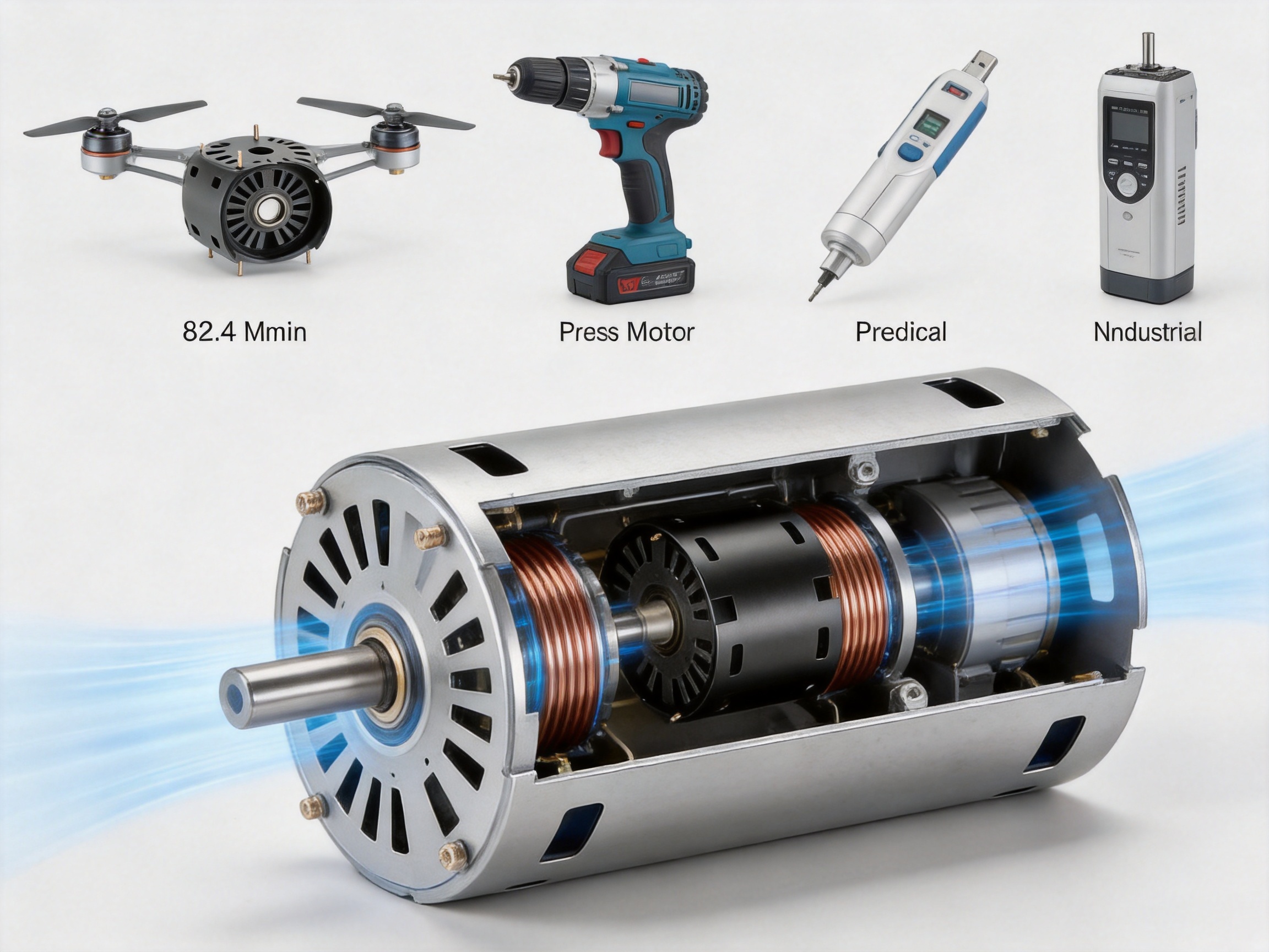
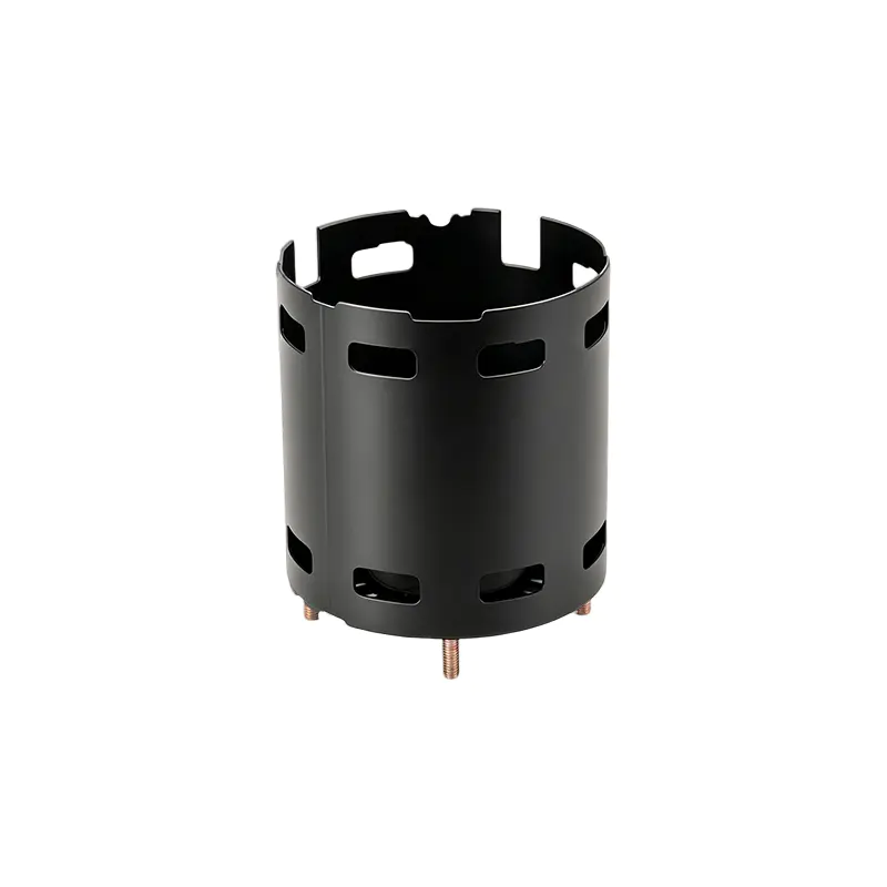
Motor housing design has a direct influence on motor durability, assembly efficiency, thermal performance, weight, and overall system reliability. As motors become smaller and more integrated, manufacturers need housings that can provide accurate internal support without adding unnecessary material or occupying valuable space. The Inner Diameter 82.4 Steel Motor Housing is developed for this purpose. It combines a compact cylindrical structure, a 1.0 mm steel wall, integrated iron end covers, welded bearing housings, pre-installed mounting studs, and axial ventilation openings in one coordinated assembly.
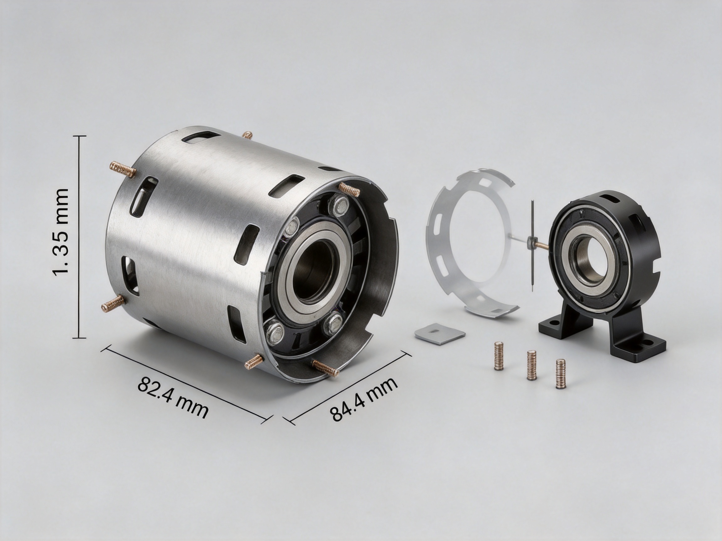
With an inner diameter of 82.4 mm, an outer diameter of 84.4 mm, and a height of 83.5 mm, this motor housing provides a controlled enclosure for compact motor assemblies. Its thin-wall construction reduces unnecessary mass while maintaining the practical rigidity required for many mobile, handheld, and precision-driven products. The design is especially suitable for applications in which every millimeter and every gram can affect the usability of the finished equipment.
Unlike a basic steel tube that requires extensive secondary processing, this housing is supplied as a more complete structural assembly. Iron end covers are combined with the cylindrical body through welding, bearing housings are welded directly into the end covers, and four welded studs are prepared for external components. Ventilation holes at both ends create a direct axial airflow path through the motor interior. These features help reduce the number of separate parts and simplify the downstream assembly process.
Manufactured by Jiangsu Yufeng Electric Co., Ltd., the product reflects a full-process manufacturing approach that includes stamping, welding, machining, assembly, and surface treatment. The company’s integrated capabilities allow the housing to be developed and produced through coordinated internal processes rather than relying solely on disconnected suppliers. This can support better process communication, more consistent quality control, and faster technical response during product development and volume production.
Product Overview
The Inner Diameter 82.4 Steel Motor Housing is a thin-wall motor enclosure designed for compact electric motor assemblies. Its principal dimensions are an 82.4 mm inner diameter, an 84.4 mm outer diameter, an 83.5 mm height, and a 1.0 mm wall thickness. The dimensional relationship between the inner and outer diameters confirms the thin-wall structure while providing a defined radial envelope for the motor’s internal components.
The steel body is combined with iron end covers on both ends. Rather than treating the end covers as simple removable plates, the design incorporates them into a welded structural assembly. This approach can improve the integrity of the enclosure and provides a practical foundation for bearing support, ventilation, and external attachment features.
Precision bearing housings are welded directly inside the end covers. This arrangement is important because bearing positioning influences rotor alignment, shaft concentricity, vibration, noise, and the service life of rotating components. By integrating the bearing support into the end-cover structure, the design reduces the number of independent pieces that must be positioned during final assembly.
Four welded studs are pre-installed on the end covers. These studs can be used for attaching controllers, mounting brackets, protective covers, or other external accessories according to the customer’s application design. Because the attachment points are prepared during housing production, customers may not need to perform additional drilling or tapping operations on the finished housing.
Ventilation holes are provided on both ends of the housing. When the motor assembly is configured appropriately, these openings establish an axial cooling path that allows air to move through the housing. The resulting airflow can assist in removing heat generated by the motor and can help support stable operation in compact equipment where natural heat dissipation is limited.
| Specification | Value |
|---|---|
| Product type | Steel motor housing |
| Product identification | ID082001 |
| Inner diameter | 82.4 mm |
| Outer diameter | 84.4 mm |
| Height | 83.5 mm |
| Wall thickness | 1.0 mm |
| Material specification | SPCC / ST12 / DC01 |
| End-cover construction | Iron end covers with welded assembly |
| Bearing support | Bearing housings welded inside end covers |
| External attachment | Four pre-installed welded studs |
| Cooling structure | Ventilation holes at both ends |
Why the 1.0 mm Thin-Wall Structure Matters
A motor housing must provide enough structural support for the motor while avoiding excessive material. A thick housing may offer a high degree of rigidity, but it can also increase total weight, consume more installation space, and require more raw material. In handheld equipment, portable tools, and aerial systems, these disadvantages can be significant. The 1.0 mm wall of this product is intended to provide a more efficient balance between enclosure strength, weight, and compactness.
The thin-wall structure is particularly relevant when the housing is used in a product with strict size and mass limits. A reduction in housing material can contribute to a lighter complete motor assembly. This may improve portability, reduce the structural burden on the surrounding equipment, or allow designers to allocate more of the available mass budget to batteries, electronics, or functional components.
Thin-wall manufacturing does require careful process control. A thinner steel section is more sensitive to deformation, welding distortion, dimensional variation, and surface damage than a heavy section. For that reason, the value of this product is not simply the use of less steel. Its value also lies in the manufacturing processes used to form, position, weld, machine, inspect, and assemble the components into a stable finished housing.
The combination of stamping and welding is suited to this type of construction. Stamping can produce repeatable cylindrical or formed components with efficient material usage, while welding can join the body, end covers, bearing supports, and studs into a functional assembly. Machining can then be used where controlled dimensions or bearing-related precision are required.
Compared with a heavier conventional housing, the thin-wall design may offer a more favorable weight-to-function ratio. Compared with an untreated tube, it provides more built-in functionality. This combination makes the product useful where a customer needs both a lightweight shell and an integrated motor support structure rather than a simple cylindrical cover.
Integrated End Covers and Structural Assembly
The two end covers are central to the performance of the housing. They close the motor enclosure, support bearing-related structures, provide locations for the welded studs, and incorporate the ventilation openings. Their design therefore affects several functions at the same time: mechanical support, alignment, thermal airflow, and external installation.
The combined welding process forms an integrated structure from the steel body and iron end covers. A well-controlled welded assembly can reduce the need for numerous fasteners and can create a stable enclosure for the motor components. It also enables the manufacturer to position multiple features during a coordinated production sequence instead of asking the customer to build the housing from several unrelated parts.
For motor manufacturers, reducing the number of separate components can provide practical benefits. Fewer loose parts may reduce picking, sorting, storage, and handling requirements. A pre-assembled housing can also shorten the customer’s production cycle and reduce the risk of installing an incorrect end cover or misaligned bearing support.
Welding must be managed carefully in a thin-wall structure. Heat input, fixture design, welding sequence, and cooling behavior all affect the final geometry. Excessive heat can produce distortion, while insufficient fusion can compromise joint integrity. Jiangsu Yufeng’s focus on stamping and automated welding equipment supports the production of repeatable assemblies and provides a foundation for controlling these variables.
The end-cover design also allows the housing to serve as more than a passive protective shell. It becomes an active mounting and alignment component within the motor system. This is an important difference between a purpose-designed motor housing and a generic steel enclosure that may require extensive customer modification.
Welded Bearing Housings for Alignment Efficiency
Bearings must be held in a stable and accurately positioned relationship with the motor shaft and rotor. If a bearing seat is incorrectly located, the resulting misalignment may contribute to vibration, friction, noise, uneven loading, and accelerated wear. Bearing support is therefore one of the most important functional areas of a motor housing.
In this product, the bearing housings are welded directly inside the iron end covers. The integrated approach is intended to ensure accurate bearing positioning and high concentricity. It also removes the need for customers to install separate bearing-support components during the basic housing assembly process.
Directly welded bearing housings can simplify the relationship between the end cover and the bearing centerline. Instead of relying on several independent parts and fastening interfaces, the bearing-support feature becomes part of the end-cover assembly. This can reduce the number of tolerance interfaces that must be managed during customer assembly.
At the same time, the complete motor design must still account for the interaction between housing dimensions, bearing dimensions, shaft geometry, rotor position, and assembly tolerances. The housing is one part of the alignment system, and appropriate technical confirmation is recommended for every motor platform. Customers should provide relevant bearing, shaft, rotor, and mounting requirements during the engineering review.
The design is especially useful for compact motors where the available internal space is limited. An integrated bearing support can help preserve the intended internal layout and reduce the need for additional brackets or thick reinforcement features. This is consistent with the overall purpose of the product: achieving functional integration within a small and lightweight envelope.
Pre-Installed Welded Studs for Faster Mounting
External attachment features are often overlooked during the initial motor design stage. However, controllers, mounting brackets, guards, cable supports, and other accessories must eventually be connected to the motor assembly. If the housing does not include suitable attachment points, the customer may need to drill holes, cut threads, add inserts, or design separate brackets.
This housing includes four welded studs on the end covers. The studs provide prepared attachment points for external components and can help customers shorten the installation process. The exact use of each stud depends on the final equipment design, but typical possibilities include controller mounting, bracket attachment, protective cover installation, and accessory support.
Welded studs can offer a practical alternative to post-production drilling and tapping. Additional machining performed by a customer may introduce burrs, chips, dimensional errors, or damage to coatings. It may also interrupt the production line and require special fixtures. By supplying the attachment features as part of the housing assembly, the manufacturer can move more of the work into a controlled production environment.
The four-stud arrangement can also improve design flexibility. Customers may have several possible mounting orientations or may need to distribute the load of an accessory around the end cover. During engineering review, the stud dimensions, spacing, weld strength, allowable load, and clearance should be confirmed against the customer’s specific application.
This built-in mounting capability gives the product an advantage over many generic steel tubes. A generic tube may provide the basic cylindrical enclosure but leave the customer responsible for creating all external attachment features. The product described here is closer to a functional motor subassembly, reducing the amount of downstream fabrication required.
Axial Ventilation and Thermal Management
Heat management is a major consideration in compact motors. Electrical losses, bearing friction, magnetic losses, and mechanical resistance generate heat during operation. When the motor is enclosed in a small housing, heat may accumulate unless the design provides a suitable path for heat transfer.
Ventilation holes at both ends of this motor housing create an axial airflow channel through the housing interior. Air can enter through one end, pass along the motor assembly, and exit through the opposite end, depending on the surrounding equipment design and the operating conditions. This direct path can assist in removing heat from the internal region.
The axial layout is compatible with the cylindrical form of the motor. It does not require a large external cooling jacket or a complex side-mounted ventilation structure. This is helpful when radial installation space is restricted or when the motor must fit within a narrow equipment body.
The ventilation openings should be evaluated together with the motor’s speed, power, duty cycle, environmental conditions, and fan or airflow arrangement. The housing can support airflow, but the final thermal result depends on the complete system. Designers should also consider dust, moisture, foreign-particle protection, acoustic requirements, and any need for filters or protective screens.
Even when the motor relies mainly on conduction through the housing, ventilation can provide an additional heat-transfer route. The steel body and end covers can conduct heat away from internal components, while airflow can assist with convective dissipation. The combination may help maintain more stable temperatures in portable tools, handheld devices, and other compact equipment.
Compared with a fully closed housing without airflow openings, this design provides a more deliberate thermal-management feature. Compared with a housing requiring complex external cooling components, it offers a simpler axial approach that can be integrated into the motor architecture.
Inner Diameter 82.4 Steel Motor Housing
Material Selection: SPCC, ST12, and DC01
The listed material specification is SPCC/ST12/DC01. These designations are commonly associated with cold-rolled low-carbon steel grades used for formed sheet-metal parts and enclosures. The exact grade, thickness tolerance, surface condition, and supply standard should be confirmed for each production order and application requirement.
Cold-rolled steel is suitable for many motor-housing applications because it offers a useful combination of formability, surface quality, dimensional consistency, and availability. These characteristics support stamping operations and provide a stable base for welding and finishing processes.
For a thin-wall motor housing, material consistency is important. Variations in sheet thickness or mechanical properties can influence forming behavior, weld response, dimensional stability, and final weight. Selecting an appropriate steel specification helps establish predictable production conditions and supports repeatable quality.
The material also provides a practical balance between performance and cost. Stainless steel may be appropriate for highly corrosive environments, but it can increase material cost and may require different forming or welding controls. A standard cold-rolled steel solution can be more economical for indoor equipment, protected assemblies, household appliances, industrial drives, and other applications where the environmental requirements do not demand stainless construction.
Surface treatment can further adapt the steel housing to its service environment. Depending on the customer’s requirements, finishing may be used to improve corrosion resistance, appearance, handling, or compatibility with the surrounding assembly. The suitable treatment should be selected based on humidity, temperature, chemical exposure, electrical grounding requirements, and customer specifications.
Manufacturing Process and Production Integration
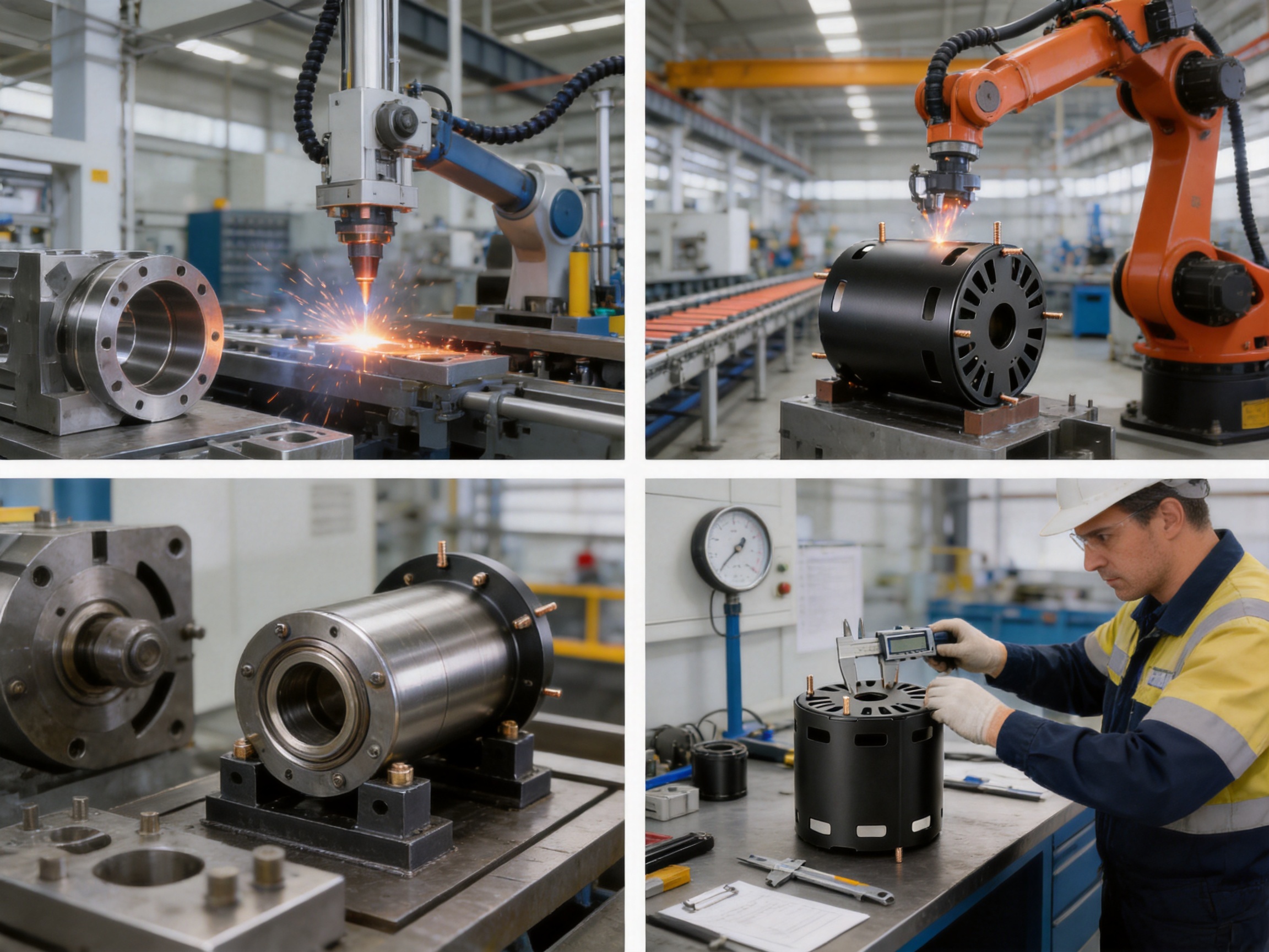
Jiangsu Yufeng Electric Co., Ltd. integrates stamping, welding assembly, machining, and surface treatment. This full-process capability is particularly relevant to a product that combines thin-wall forming with welded end-cover structures and precision bearing supports.
Stamping and Forming
Stamping provides an efficient method for producing repeatable steel components. The process can be used to form the cylindrical body, end-cover features, ventilation openings, and other shaped details. Proper die design helps control dimensions, reduce material waste, and maintain consistent geometry across production batches.
Thin sheet requires carefully controlled forming conditions. The tooling must support the material without creating excessive wrinkling, cracking, or springback. Process engineers may need to evaluate blank layout, forming sequence, punch and die clearance, lubrication, and part removal. The aim is to create a stable component that can move into welding without excessive corrective work.
Repeatable stamping is especially valuable for motor housings because the cylindrical body and end covers must work together. Dimensional variation in the body can affect the fit of the end covers, while variation in the end covers can influence bearing alignment and overall height. Coordinated stamping control helps maintain the relationship among these features.
Welding Assembly
Welding joins the steel body, iron end covers, bearing housings, and welded studs into a functional assembly. Automated welding equipment can improve repeatability by controlling the welding path, fixture position, current, timing, and other key parameters. Automation also helps reduce variation caused by manual positioning.
Fixtures are essential for a thin-wall welded housing. They must hold the cylindrical body and end covers in the correct relationship while allowing sufficient access for the welding process. A suitable fixture can reduce movement during welding and help maintain the intended height, concentricity, and overall geometry.
The welding sequence is also important. If heat is concentrated in one area, the housing may distort or develop residual stress. A balanced sequence can distribute heat more evenly and reduce the risk of deformation. Post-weld inspection can then verify critical dimensions and identify any defects requiring correction.
Welding the bearing housings directly inside the end covers requires additional attention because the bearing-support location is functionally critical. Positioning, fixture accuracy, weld stability, and subsequent machining all contribute to the final bearing relationship. This integrated process is a key technical aspect of the product.
Machining and Precision Finishing
Machining is used where formed and welded parts require more precise dimensional control. Bearing-related surfaces, locating features, mounting interfaces, or other functional areas may require machining after welding. This can help compensate for process variation and create the final geometry needed by the motor assembly.
Machining after welding should be planned with consideration for distortion and reference selection. The manufacturer must establish appropriate datum points and ensure that the machined features remain correctly related to the housing centerline. Inspection instruments are used to evaluate dimensions and confirm that the part meets the agreed technical requirements.
The combination of forming, welding, and machining enables the manufacturer to use each process where it is most effective. Stamping provides production efficiency, welding creates integrated construction, and machining establishes controlled precision at critical locations. This is more capable than relying on a single process to produce every feature.
Surface Treatment
Surface treatment can protect the steel from corrosion and provide the desired appearance or functional finish. The correct treatment depends on the customer’s environment and assembly conditions. It may be necessary to consider coating thickness, adhesion, grounding, masking of bearing areas, and compatibility with lubricants or adhesives.
Because Jiangsu Yufeng provides surface-treatment capability as part of its manufacturing scope, finishing can be coordinated with the preceding forming, welding, and machining processes. This may help reduce handling between suppliers and simplify responsibility for the finished housing.
Quality Control for a Thin-Wall Motor Housing
Quality control should cover both visible appearance and functional geometry. A housing may look acceptable externally but still have a bearing support that is out of position, a distorted end cover, an incorrect stud location, or a ventilation opening that does not meet the design requirement. A complete inspection approach therefore evaluates the entire assembly.
Dimensional inspection can include inner diameter, outer diameter, height, wall thickness, end-cover position, bearing-support location, stud spacing, and ventilation-hole dimensions. Measurement methods should be selected according to the required accuracy and production volume. Gauges may be used for fast production checks, while coordinate measurement or specialized instruments may be used for detailed verification.
Weld inspection should evaluate joint appearance, continuity, penetration where applicable, spatter, cracks, porosity, undercut, and deformation. The inspection standard should be agreed with the customer based on the housing’s function and service conditions. Critical bearing-support welds may require more stringent control than non-structural attachment welds.
Concentricity and alignment are especially important. The housing must provide a stable relationship between the cylindrical body, end covers, bearing supports, and motor shaft. Inspection planning should identify the relevant datums and verify the features that affect rotor positioning and bearing operation.
Material verification may include review of supplier certificates, grade confirmation, thickness measurement, and traceability. For volume production, lot control helps connect the raw material to the finished housing and supports investigation if a quality issue occurs.
Surface inspection can check coating coverage, scratches, dents, weld discoloration, sharp edges, and contamination. These factors influence appearance, corrosion resistance, safety, and ease of assembly. Deburring and edge control are particularly important where the housing will be handled by operators or installed near cables and other components.
Advantages Compared with Conventional Housing Solutions
The first advantage is integration. A conventional steel tube may serve as a motor shell, but it often requires separate end covers, bearing seats, mounting parts, and customer-side machining. The Inner Diameter 82.4 Steel Motor Housing combines these functions into one coordinated product, reducing the amount of work required after delivery.
The second advantage is weight efficiency. A 1.0 mm wall is thinner than many heavy-wall housing designs and can reduce the mass of the enclosure. This is valuable for portable equipment, handheld products, and aerial systems in which the total assembly must remain light.
The third advantage is installation simplicity. Four welded studs provide prepared attachment points for external accessories. Customers can avoid some drilling, tapping, and bracket fabrication operations, potentially shortening assembly time and improving production consistency.
The fourth advantage is alignment support. Bearing housings welded directly into the end covers provide an integrated location for the bearings. This can reduce the number of loose alignment components and simplify the assembly sequence.
The fifth advantage is thermal functionality. Ventilation holes at both ends create an axial airflow path. A generic closed enclosure may offer less opportunity for direct internal airflow, while a housing with poorly positioned openings may not support an efficient flow direction.
The sixth advantage is manufacturing coordination. Stamping, welding, machining, assembly, and finishing are available through one specialized manufacturer. This can simplify communication regarding drawings, tolerances, process changes, samples, and production issues.
These advantages do not mean that the product is suitable for every motor. Heavy industrial motors, highly corrosive environments, explosion-protected equipment, and high-pressure sealed systems may require different materials, wall thicknesses, sealing arrangements, or certification. However, for compact motors requiring low weight, functional integration, and reliable production, the product offers a strong combination of features.
Application Areas
Drone Motors
Drone systems are highly sensitive to weight and packaging efficiency. A motor housing that reduces unnecessary mass can support the overall weight targets of the aircraft. The compact 82.4 mm inner diameter and 83.5 mm height provide a defined envelope for a motor assembly, while the thin-wall construction helps avoid excessive structural material.
Drone applications also require careful attention to vibration, rotor balance, bearing alignment, and heat dissipation. The integrated bearing supports and axial ventilation concept can contribute to a suitable motor architecture, subject to validation under the specific speed, load, and environmental conditions of the aircraft.
Portable Power Tools
Portable power tools require a durable motor enclosure that can fit within an ergonomic product body. Users may carry and operate the tool for extended periods, making weight, heat, vibration, and reliability important considerations. The lightweight steel construction can help reduce the burden on the operator without abandoning the rigidity of a metal housing.
The pre-installed studs may also provide practical mounting options for controllers, guards, or internal brackets. The ventilation holes can support airflow through the motor, although designers must consider dust protection and the operating environment of the specific tool.
Medical Handheld Devices
Medical handheld equipment often requires compact, cleanly manufactured, and reliably assembled motor modules. The integrated housing design can reduce the number of loose parts and provide a more controlled base for the motor assembly. Material selection and surface treatment should be reviewed carefully for the applicable hygiene, cleaning, and regulatory requirements.
For medical applications, customers should also define requirements for traceability, documentation, dimensional validation, cleanliness, and any applicable industry standards. The housing can be adapted through engineering review, but final suitability depends on the complete device and its intended use.
Precision Instruments
Precision instruments may require compact motors with stable bearing positioning and controlled vibration. The welded bearing-support arrangement is relevant to this need because it is designed to provide a defined relationship between the bearing location and the housing end cover.
The housing’s small external envelope may also help designers preserve space for sensors, control electronics, optical components, or other instrument functions. As with all precision applications, customers should validate concentricity, runout, vibration, noise, and thermal behavior in the assembled motor.
Household Appliances and Industrial Drives
The company’s broader product experience includes household appliances, industrial drives, new energy vehicles, and special equipment. The 82.4 mm housing is optimized for compact applications, but the manufacturing capabilities behind it can also support the development of related housing products with different dimensions, materials, attachment features, and surface treatments.
For household appliances, the housing may be evaluated for noise, cost, production volume, corrosion resistance, and integration with molded or stamped surrounding parts. For industrial drives, customers may focus more strongly on dimensional stability, duty cycle, thermal performance, and long-term mechanical reliability.
Engineering and Customization Considerations
Although the listed product has defined dimensions, motor housings are often part of a larger customized assembly. Before production, customers should provide drawings or specifications for the motor shaft, bearings, rotor, stator, controller, wiring, mounting brackets, and surrounding equipment.
Important engineering information includes the required bearing type and size, bearing seat tolerance, shaft centerline, rotor clearance, stator fit, axial stack length, cable exit position, ventilation requirements, mounting direction, and environmental conditions. Providing this information early helps the manufacturer evaluate compatibility and identify possible interference.
The four welded studs should be reviewed against the customer’s attachment design. Relevant factors include stud diameter, length, spacing, thread requirements if applicable, allowable load, torque during assembly, and clearance from internal motor components. If the studs are used to support a controller or bracket, the customer should also assess vibration and impact loads.
Ventilation openings should be reviewed for both airflow and protection. If the motor operates in a dusty or wet environment, the customer may need filters, screens, labyrinth structures, or a different enclosure configuration. The correct solution depends on the balance between cooling, ingress protection, acoustic performance, and serviceability.
Surface treatment can be selected according to the operating environment. Indoor applications may require a different finish from outdoor, humid, salt-exposed, chemically exposed, or high-temperature applications. Masking may also be needed around bearing seats, grounding points, or areas that must remain dimensionally controlled.
For new projects, prototype sampling is recommended before mass production. Prototype evaluation may include dimensional inspection, trial assembly, welding review, bearing installation, rotor rotation, vibration testing, thermal testing, and endurance testing. Feedback from the prototype stage can be used to refine tooling, tolerances, welding fixtures, and finishing requirements.
Benefits of Full In-House Production
Full in-house production can improve communication between engineering and manufacturing. When stamping, welding, machining, assembly, and finishing are coordinated within one organization, process changes can be evaluated with a broader view of the complete product rather than only one operation.
This structure can also reduce the number of supplier interfaces. A customer may otherwise need to coordinate a stamped body supplier, a welding supplier, a machining supplier, and a finishing supplier separately. A single manufacturing partner can simplify purchase management, technical documentation, quality responsibility, and delivery coordination.
Jiangsu Yufeng Electric has an engineering team with an average of more than 20 years of experience. This experience supports technical work from product development through mass production. For motor housing projects, such knowledge can be valuable when addressing forming feasibility, welding distortion, bearing alignment, tooling design, inspection planning, and process optimization.
The company reports 40 years of experience in motor housing manufacturing, service to more than 50 customers, and annual production capacity exceeding 5 million units. These figures indicate experience in both product development and higher-volume manufacturing. Capacity alone does not guarantee that every project will meet its requirements, but it provides an important foundation for customers seeking a supplier capable of supporting scale-up.
Inspection instruments and production equipment are also important. A housing supplier must be able to verify not only raw dimensions but also the relationships among critical features. The company’s stated combination of stamping lines, automated welding equipment, machining facilities, and inspection instruments is aligned with the technical demands of an integrated thin-wall housing.
Production Efficiency and Customer Value
Customer value is determined by more than the purchase price of the housing. It also includes assembly labor, tooling investment, inspection time, inventory complexity, quality risk, and the cost of late engineering changes. An integrated housing can create value by reducing some of these indirect costs.
Pre-installed welded studs may reduce customer-side drilling and tapping. Integrated bearing housings may reduce the number of separate components. Welded end covers may simplify enclosure assembly. Axial ventilation openings may eliminate the need for additional cooling features in some designs. Together, these characteristics can improve the efficiency of the complete motor production process.
A stable supply chain is also important for volume programs. Coordinated production can help align raw material purchasing, stamping, welding, machining, surface treatment, inspection, packaging, and shipment. For customers with recurring demand, the supplier should establish appropriate production planning, lot control, quality documentation, and change-management procedures.
The product can therefore be evaluated as a motor-housing solution rather than simply as a formed steel part. Its competitive value comes from the relationship among dimensions, integrated features, manufacturing process, and supplier capability.
Assembly Guidance and Handling
Before assembly, customers should inspect the housing for visible damage, contamination, burrs, deformation, incorrect studs, and blocked ventilation openings. The bearing-support areas should be protected from impact and contamination during handling. Thin-wall components can be damaged by improper stacking or excessive clamping force.
During bearing installation, the assembly force should be applied appropriately to the bearing ring associated with the interference fit. Improper force transfer can damage the bearing or distort the support structure. The customer’s assembly procedure should also control cleanliness and prevent particles from entering the bearing or motor interior.
When installing the rotor and stator, the customer should verify radial and axial clearances. The welded end covers and bearing supports must remain free from interference with rotating components. Any abnormal resistance, rubbing, noise, or misalignment should be investigated before the motor is energized.
External components attached to the welded studs should be installed with suitable torque and hardware. Excessive torque may damage the stud or end cover, while insufficient torque may allow loosening under vibration. If thread-locking materials are used, their compatibility with the surface treatment and operating temperature should be confirmed.
Ventilation must remain functional after the motor is installed into the final equipment. Surrounding brackets, cables, controllers, seals, or covers should not block the intended airflow path. If the application requires a protective mesh or filter, its pressure drop and maintenance requirements should be evaluated.
Testing and Validation
A complete validation program should reflect the intended application. Basic tests may include dimensional verification, trial assembly, bearing fit confirmation, rotor rotation, and visual inspection. More advanced tests may include vibration, noise, thermal rise, endurance, impact, corrosion, and environmental exposure.
Thermal testing should be performed at representative voltage, current, speed, load, duty cycle, and ambient temperature. The end-cover ventilation openings should be evaluated under the actual system airflow conditions. If the motor is installed inside a restricted enclosure, the test should reproduce the surrounding structure because airflow can change significantly after integration.
Mechanical testing may include vibration and shock testing, especially for drone motors, portable tools, and mobile equipment. The test should verify that the welded joints, bearing supports, studs, and end covers remain stable under the expected loads.
Corrosion testing depends on the selected material and surface treatment. If the housing will operate in a humid, outdoor, or chemically exposed environment, the finish should be validated against the relevant conditions. The customer and supplier should agree on acceptance criteria before testing.
Endurance testing can help evaluate the interaction among housing rigidity, bearing alignment, thermal behavior, and motor loading. Long-duration operation may reveal issues that are not visible during short functional tests. A coordinated validation plan helps ensure that the housing is assessed as part of the complete motor rather than in isolation.
How the Product Supports Modern Compact Equipment
Modern equipment increasingly combines motors, controllers, sensors, batteries, communication modules, and mechanical structures within limited spaces. This trend increases the importance of component integration. A motor housing that includes bearing support, mounting features, ventilation, and structural enclosure functions can help designers use the available space more efficiently.
Weight reduction is also important in battery-powered products. Lower housing mass can contribute to longer operating time, easier handling, reduced transportation weight, or improved mobility. The 1.0 mm wall is a direct response to this need, provided that the complete assembly is properly designed and validated.
Manufacturing flexibility is equally important. Product developers may need to move quickly from prototype to volume production, adjust mounting features, or adapt the housing to a new motor platform. A manufacturer with internal stamping, welding, machining, assembly, and finishing capabilities can support these transitions more effectively than a supplier limited to one operation.
The Inner Diameter 82.4 Steel Motor Housing demonstrates how a relatively compact component can incorporate multiple engineering objectives. It is lightweight, structurally integrated, prepared for external mounting, designed for bearing support, and equipped for axial airflow. These characteristics make it a practical option for product designers seeking a more complete motor-housing solution.
Frequently Asked Questions
What is the inner diameter of the housing?
The inner diameter is 82.4 mm. This dimension defines the primary internal cylindrical space available for the motor assembly and should be reviewed together with stator, rotor, insulation, and clearance requirements.
What are the outer diameter and height?
The listed outer diameter is 84.4 mm, and the height is 83.5 mm. These dimensions define the principal external envelope of the housing.
What is the wall thickness?
The wall thickness is 1.0 mm. This thin-wall construction is intended to reduce weight and preserve compactness while providing the structural support required by the motor design.
What material is used?
The stated material specification is SPCC/ST12/DC01. These are cold-rolled steel designations commonly used for formed sheet-metal components. The exact material standard, thickness tolerance, and surface condition should be confirmed for the specific order.
Does the product include end covers?
Yes. The housing is equipped with iron end covers on both ends. The end covers are combined with the housing body through welding to form an integrated structure.
Are bearing housings included?
Yes. Precision bearing housings are welded directly inside the end covers. This arrangement is intended to support accurate bearing positioning and high concentricity.
How many mounting studs are provided?
Four welded studs are pre-installed on the end covers. They can be used for attaching controllers, mounting brackets, protective components, or other external accessories according to the customer’s design.
Does the housing support motor cooling?
Ventilation holes are provided on both ends. These openings establish an axial airflow path through the housing interior and can assist in heat dissipation. Final cooling performance depends on the motor, airflow conditions, load, duty cycle, and surrounding equipment design.
Can the housing be used for drone motors?
Yes. The compact dimensions and lightweight thin-wall construction make it suitable for consideration in drone motor applications. Customers should validate vibration, balance, thermal performance, bearing life, and environmental resistance for the specific aircraft system.
Is it suitable for portable power tools?
Yes. The product is particularly suitable for compact portable power tools where low weight, metal rigidity, ventilation, and integrated mounting features are important. Dust protection and impact requirements should be reviewed during product development.
Can the housing be customized?
Customization should be discussed with the manufacturer. Potential engineering variables may include dimensions, material, stud arrangement, ventilation design, bearing-support geometry, surface treatment, and other motor-specific features. A drawing and application specification are recommended for technical evaluation.
What manufacturing processes are available?
The manufacturer provides stamping, welding, machining, assembly, and surface treatment. These capabilities support the production of integrated motor housings from formed steel components through finished assemblies.
What should customers provide before requesting production?
Customers should provide the motor drawing, housing dimensions, bearing information, shaft and rotor requirements, mounting details, ventilation expectations, surface-treatment requirements, operating environment, annual demand, inspection criteria, and applicable standards.
Does the housing provide a completely sealed enclosure?
The welded body and end covers form an integrated structure, but the ventilation holes mean that the standard design is not a fully sealed enclosure. If a sealed or protected configuration is required, customers should discuss alternative openings, seals, filters, or enclosure modifications with the manufacturer.
How should the housing be validated?
Validation may include dimensional inspection, trial assembly, bearing-fit verification, rotor clearance checks, vibration testing, thermal testing, endurance testing, corrosion evaluation, and environmental testing. The final test plan should reflect the application and agreed technical requirements.
Conclusion
The Inner Diameter 82.4 Steel Motor Housing is designed for motor applications that require compact dimensions, low weight, integrated structure, and efficient assembly. Its 82.4 mm inner diameter, 84.4 mm outer diameter, 83.5 mm height, and 1.0 mm wall thickness provide a defined lightweight platform for compact motor systems.
The product’s advantages come from the combination of several features. Iron end covers are welded to the body, bearing housings are integrated into the end covers, four welded studs provide prepared external attachment points, and ventilation holes create an axial cooling channel. Together, these features offer more functionality than a basic steel tube or a housing that requires extensive customer-side modification.
Its suitability for drone motors, portable power tools, medical handheld devices, precision instruments, and other mobile applications reflects the growing demand for lightweight and space-efficient motor components. At the same time, the design can be evaluated for household appliances, industrial drives, and specialized equipment when the dimensions and environmental requirements are appropriate.
Jiangsu Yufeng Electric Co., Ltd. supports this product through integrated stamping, welding, machining, assembly, surface treatment, and inspection capabilities. Its stated experience in motor housing manufacturing, engineering resources, production equipment, and annual capacity provide a foundation for both development projects and volume production.
For customers seeking a motor housing that combines thin-wall efficiency with practical structural integration, this product offers a well-balanced starting point. Final performance should always be confirmed through application-specific engineering review, prototype assembly, dimensional inspection, and functional validation.
References
1. Product Specification Sheet, ID082001, Inner Diameter 82.4 Steel Motor Housing.
2. Jiangsu Yufeng Electric Co., Ltd., Corporate Manufacturing and Capability Information.
3. General Engineering Principles for Stamped Steel Enclosures and Motor Housing Assemblies.
4. General Practices for Welded Bearing Supports, Concentricity Control, and Motor Assembly Alignment.
5. General Design Considerations for Axial Ventilation and Thermal Management in Compact Electric Motors.
6. General Material Reference Information for SPCC, ST12, and DC01 Cold-Rolled Steel Grades.

 Previous