

 English
 Español
Content
- 1 Product Overview
- 2 Why a Heavy-Wall Housing Matters
- 3 Integrated Welded Base for Stable Mounting
- 4 Flexible Threaded Interfaces
- 5 Compact Dimensions with Substantial Strength
- 6 Applications in Aerial Work Platforms
- 7 Material and Fabrication Advantages
- 8 Manufacturing Process from Steel to Finished Housing
- 9 Advantages over Generic and Light-Duty Alternatives
- 10 Supplier Manufacturing Strengths
- 11 Quality Considerations for Customers
- 12 Installation and Service Recommendations
- 13 Customization and Project Development
- 14 Purchasing and Evaluation Checklist
- 15 Environmental and Safety Considerations
- 16 Overall Product Value
- 17 Questions and Answers
- 17.1 What is the inner diameter of the motor housing?
- 17.2 What is the height of the housing?
- 17.3 What is the wall thickness?
- 17.4 What material is used?
- 17.5 Does the product include a mounting base?
- 17.6 How many side screw holes are provided?
- 17.7 How many threaded holes are located on the end faces?
- 17.8 Which equipment is this housing designed for?
- 17.9 Is the housing suitable for every motor with a 123.8 mm diameter?
- 17.10 Can the housing be customized?
- 17.11 Does the housing itself define the motor’s environmental protection rating?
- 17.12 What should be checked before installation?
- 17.13 Why is integrated manufacturing useful for this product?
- 17.14 What information should be included in an inquiry?
- 18 References
- 19 Product: Inner Diameter 123 Heavy-Wall Motor Housing With Base
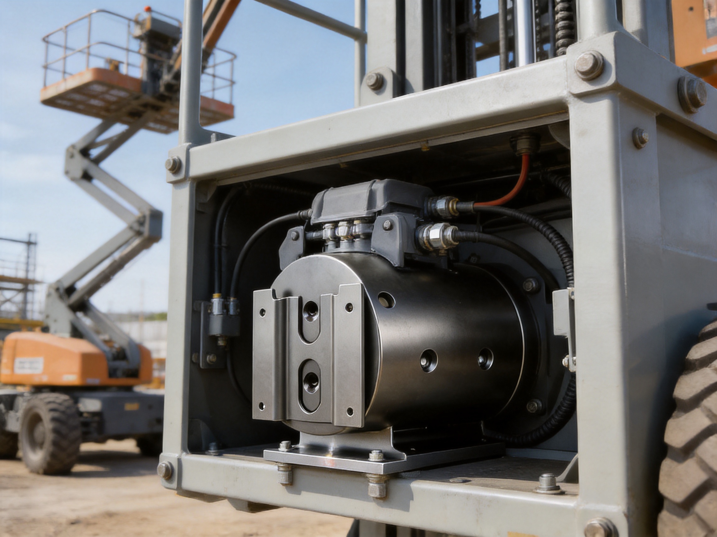
Reliable motor protection begins with a housing that can withstand the mechanical, environmental, and installation demands of the equipment in which it operates. For aerial work platforms, scissor lifts, mobile cranes, service vehicles, and other special-purpose machines, a motor housing is more than a simple cover. It is a structural component that protects the motor, supports related parts, maintains alignment, provides mounting interfaces, and contributes to the safety and service life of the complete assembly.
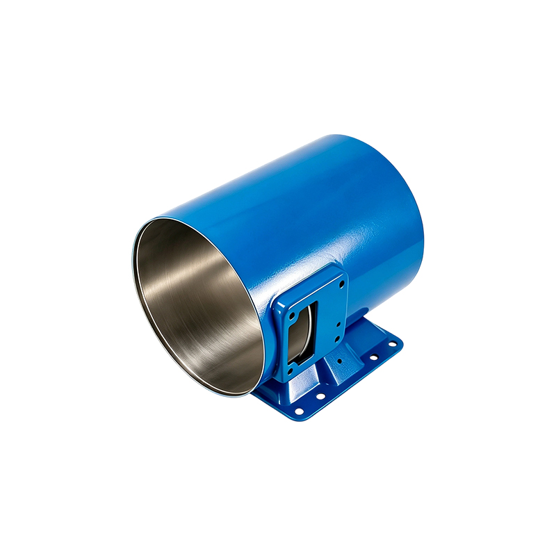
The Inner Diameter 123 Heavy-Wall Motor Housing With Base is designed for these demanding conditions. Manufactured from 20# steel, the housing has an inner diameter of 123.8 mm, a height of 166 mm, and a wall thickness of 9.6 mm. Its welded base provides a stable mounting platform, while multiple threaded interfaces support flexible assembly and expansion. This combination creates a compact but robust steel tube motor housing suitable for motor systems exposed to vibration, impact, changing loads, and frequent movement.
Compared with lighter-duty motor housings, this design emphasizes structural strength, mounting reliability, and installation flexibility. Compared with generic steel tubes that require extensive secondary modification, it provides a more complete component configuration, including the welded base, side screw holes, and threaded holes on both end faces. As a result, customers can reduce assembly complexity while obtaining a housing that is better suited to specialized motor applications.
Product Overview
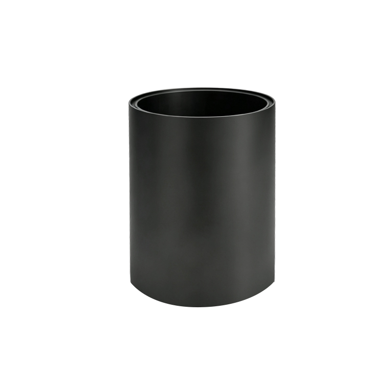
The product is a heavy-wall steel motor housing with an integrated welded base. Its cylindrical body is formed around a 123.8 mm internal diameter and has a total height of 166 mm. The 9.6 mm wall thickness gives the housing a substantial structural section, helping it resist deformation during installation and operation. The material specification is 20# steel, a commonly used low-carbon structural steel grade suitable for fabrication, welding, machining, and general mechanical applications when properly processed.
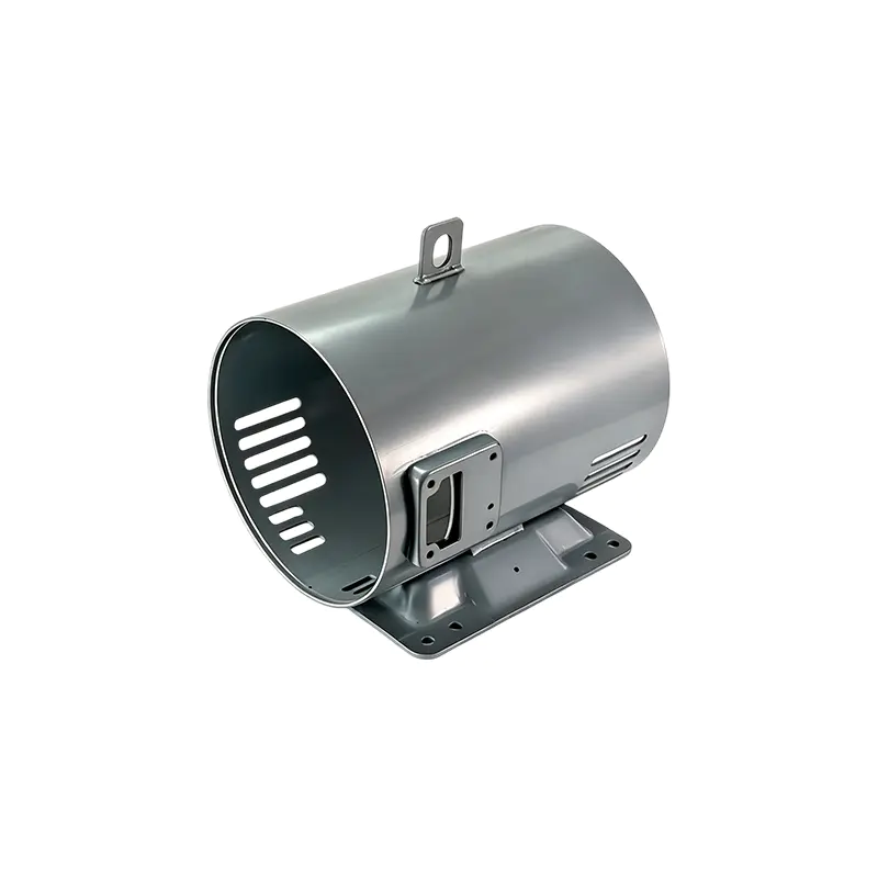
The housing is categorized as a steel tube motor housing, but it is engineered as a finished or semi-finished motor component rather than an ordinary length of tube. Its body, base, holes, and end interfaces are designed to work together as an integrated assembly. The design supports accurate positioning of end covers or flanges, secure attachment of auxiliary components, and reliable fixation to the supporting equipment.
The welded base is one of the most important features of the product. A motor installed in an aerial work platform or mobile machine may be subjected to repeated vibration, sudden acceleration and deceleration, impact during movement, and load changes during lifting or positioning. A weak or poorly aligned base can cause fastener loosening, excessive vibration, uneven loading, or premature failure of connected parts. The integrated base is intended to provide a firm mounting foundation for the complete motor unit.
Eight screw holes are provided on the side of the housing. These holes can be used for fixing auxiliary components, guards, brackets, cable management parts, or protective covers, depending on the final customer design. Both end faces include four threaded holes, creating a total of eight end-face threaded interfaces. These holes assist with the positioning and fastening of end covers, flanges, or other motor-related parts.
| Item | Specification | Functional Significance |
|---|---|---|
| Product type | Heavy-wall steel tube motor housing with base | Provides motor protection, support, and assembly interfaces |
| Inner diameter | 123.8 mm | Defines the internal motor installation space |
| Height | 166 mm | Establishes the principal axial dimension of the housing |
| Wall thickness | 9.6 mm | Supports rigidity and resistance to mechanical deformation |
| Material specification | 20# steel | Suitable for steel fabrication, welding, machining, and industrial use |
| Side interfaces | 8 screw holes | Supports auxiliary component and protective cover installation |
| End interfaces | 4 threaded holes on each end face | Supports positioning and fastening of end covers or flanges |
| Base | Welded steel base | Provides a stable mounting connection for the complete unit |
Why a Heavy-Wall Housing Matters
Motor housings must perform several functions simultaneously. They must contain and protect the motor, preserve the relationship between internal and external components, provide a reliable mounting structure, and withstand the operating environment. In stationary equipment, the mechanical demands may be relatively predictable. In mobile equipment, the housing can experience many different force conditions over a short operating cycle.
Aerial work platforms are a typical example. The machine may move across uneven ground, extend or retract lifting mechanisms, carry changing loads, and operate at different heights. These actions create vibration and dynamic forces that are transmitted through the equipment structure to the motor assembly. The housing must therefore remain rigid and securely fixed while the motor performs its normal function.
Wall thickness is a key factor in this situation. A 9.6 mm wall provides a substantial material section compared with thin-wall housings intended for light-duty applications. Greater wall thickness can improve resistance to local denting, distortion around holes, and deformation caused by external forces. It can also provide more material for machining and threaded features, subject to the final engineering design and processing requirements.
Heavy-wall construction also supports a more stable connection between the housing and attached components. When covers, brackets, or flanges are tightened, the housing must distribute clamping forces without excessive local deformation. A more rigid body can help maintain the intended geometry and reduce the likelihood of alignment changes during service.
However, strength is not determined by wall thickness alone. Material selection, forming quality, weld design, heat input, dimensional control, machining accuracy, and inspection all influence the final performance of the component. The value of this product comes from the combination of its heavy-wall geometry, welded base, threaded interfaces, and controlled manufacturing process.
Integrated Welded Base for Stable Mounting
The welded base transforms the housing from a cylindrical protective shell into a mounting-ready structural component. Instead of requiring the customer to design and fabricate a separate support bracket, the housing can be connected directly to the equipment structure through its base, subject to the customer’s installation drawings and load requirements.
A properly manufactured welded base provides several practical benefits. It can reduce the number of separate parts in the assembly, simplify the installation process, and decrease the amount of alignment work required at the customer’s facility. Fewer separate components can also reduce the number of interfaces where looseness, wear, or dimensional mismatch might occur.
Welding must be controlled carefully because the process introduces heat into the steel structure. Excessive or uneven heat input can cause distortion, residual stress, or changes in the geometry of the mounting surface. For a motor housing, even modest distortion may affect the alignment of the motor, end cover, coupling, or connected drive components. Professional welding procedures and subsequent inspection are therefore important to the quality of the finished product.
The base is intended to withstand the continuous vibration and impact loads associated with aerial work platforms and similar mobile equipment. The exact allowable loads depend on the final assembly, weld design, mounting method, operating conditions, and safety requirements. Nevertheless, the integrated configuration provides a stronger starting point than a simple unreinforced tube that has not been prepared for equipment mounting.
For equipment designers, the base can also provide a clearer path for load transfer. Motor reaction forces and external mounting loads can be transferred from the housing body through the welded base into the machine frame. This makes it easier to develop a complete mounting concept in which the motor housing, fasteners, brackets, and machine structure are considered together.
Flexible Threaded Interfaces
The product includes eight screw holes on the side of the housing. These interfaces are valuable because motor systems often require more than the primary motor body. Depending on the application, a customer may need to mount a protective guard, cable support, sensor bracket, terminal cover, cooling-related component, or other auxiliary part.
When such holes are designed into the housing from the beginning, customers do not need to create as many custom modifications after delivery. This can reduce drilling, rework, and the risk of damaging the housing. It also makes the final assembly more standardized. Auxiliary components can be designed around known hole positions, and replacement parts can follow the same interface arrangement.
The four threaded holes on each end face provide another important installation advantage. End covers and flanges frequently require accurate positioning relative to the motor shaft, bearing arrangement, or connected equipment. Threaded interfaces on both ends support controlled fastening and allow the end components to be secured without relying entirely on external clamps or improvised brackets.
The combination of side screw holes and end-face threaded holes creates a modular platform. A motor housing with only a smooth outer surface may protect the motor but offer limited adaptability. This product is more suitable for applications in which the housing must accommodate several connected parts or be integrated into a larger mechanical system.
Threaded interfaces also support maintenance and service operations. If an end cover or auxiliary guard must be removed, a defined fastener pattern can make disassembly more straightforward. Correct fastener selection, tightening torque, thread engagement, and use of locking methods remain the responsibility of the final system designer, but the housing provides a structured foundation for these decisions.
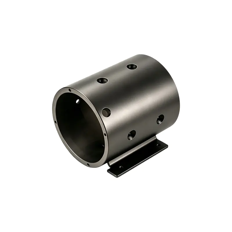
Inner Diameter 123 Heavy-Wall Motor Housing With Base
Compact Dimensions with Substantial Strength
The housing has a 123.8 mm inner diameter and a 166 mm height. These dimensions create a compact form for motor applications that require a relatively strong enclosure without a large external footprint. Compactness is particularly important in aerial work platforms and special vehicles, where equipment layout is restricted by frames, hydraulic systems, batteries, control cabinets, and operator-safety requirements.
A compact housing can simplify packaging and help equipment manufacturers make more efficient use of limited installation space. It may also reduce the distance between the motor and adjacent transmission or hydraulic components. The final external diameter will depend on the wall thickness and manufacturing tolerances, but the specified internal diameter and wall thickness provide a clear basis for design calculations.
The 166 mm height establishes the axial space available for the motor assembly. Customers should verify the complete motor stack length, end cover dimensions, shaft extension, bearing arrangement, terminal position, and required clearances before confirming compatibility. When integrated with the appropriate motor design, the housing can support a compact and robust power unit for mobile machinery.
Compact construction should not be confused with minimal construction. The design aims to combine a relatively controlled overall size with a 9.6 mm wall thickness and a substantial mounting base. This balance is useful for customers who need structural durability but cannot accommodate a large, heavy, or highly customized enclosure.
Applications in Aerial Work Platforms
Aerial work platforms rely on dependable systems because failures can interrupt work and create safety concerns. Their motors may support traction, lifting, steering, auxiliary hydraulic functions, or other equipment operations. In many designs, the motor is exposed to repeated start-stop cycles, vibration from travel, and changing loads generated by platform elevation and movement.
The heavy-wall housing is suited to these conditions because it provides a rigid enclosure and a prepared mounting structure. The welded base can be connected to the platform frame or a dedicated motor support, while the side and end interfaces can accommodate protective and functional components. The result is a housing concept that addresses both protection and integration.
For scissor lifts, the operating environment may include frequent movement over uneven surfaces, rapid changes in platform position, and limited service access. A housing that is stable, compact, and equipped with defined interfaces can support easier equipment layout and maintenance planning. The final design must still account for vibration isolation, drainage, cable routing, and the protection level required by the machine.
Mobile cranes and service vehicles present similar challenges. Motors can be exposed to road vibration, mechanical shock, temperature changes, dust, moisture, and repeated loading cycles. A steel housing with a substantial wall and welded base provides a durable mechanical foundation, while the threaded interfaces support the installation of guards and related equipment.
The product may also be considered for other special vehicles and industrial systems that require a motor housing with high structural strength and flexible installation. Potential applications include compact lifting systems, mobile maintenance equipment, electrically driven auxiliary systems, and customized machinery. Suitability should be verified through dimensional review, load analysis, environmental evaluation, and prototype testing.
Material and Fabrication Advantages
The specified material is 20# steel. This material is commonly selected for components that require a practical balance of strength, formability, machinability, weldability, and cost. Its suitability for a particular application depends on the relevant material standard, chemical composition, mechanical properties, heat treatment condition, and customer requirements.
For motor housings, steel offers several benefits. It provides good resistance to mechanical impact, supports welded fabrication, and can be machined to create accurate mounting or fastening features. It can also be treated or coated to improve resistance to corrosion in the intended environment. The appropriate surface treatment should be selected according to humidity, salt exposure, chemicals, temperature, and service life expectations.
The production of a housing like this typically requires coordination among steel preparation, tube forming or processing, cutting, hole making, welding, machining, surface treatment, and inspection. Each step affects the next. For example, inaccurate tube preparation can affect base alignment; welding distortion can affect end-face machining; and inadequate surface preparation can reduce coating adhesion.
Jiangsu Yufeng Electric Co., Ltd. states that it integrates stamping, welding assembly, machining, and surface treatment within its manufacturing operations. This type of in-house process integration is an important advantage for customers seeking consistent production control. When multiple operations are managed within one manufacturing system, engineering information, quality records, and process feedback can be coordinated more effectively.
In-house production can also improve response speed during product development. If a customer needs a dimensional adjustment, hole-position change, welding modification, or surface-treatment variation, the manufacturer can evaluate the change across the relevant processes rather than relying entirely on separate external suppliers. This can shorten communication cycles and reduce the risk of mismatched specifications.
Manufacturing Process from Steel to Finished Housing
Engineering Review and Production Planning
Manufacturing begins with a review of the product drawing, three-dimensional model, material specification, dimensional tolerances, hole pattern, welding requirements, surface-treatment requirements, and inspection standards. For a motor housing, the manufacturer must understand not only the nominal dimensions but also the functional relationships among the inner diameter, end faces, threaded holes, base position, and mounting surfaces.
Production planning determines the sequence of operations and the equipment required. The sequence should minimize distortion, protect finished surfaces, and allow critical dimensions to be checked at appropriate stages. Planning is especially important when the housing includes welded and machined features because the part may change shape slightly during fabrication.
Steel Preparation and Tube Processing
The 20# steel raw material is prepared according to the approved production specification. Depending on the manufacturing route, the tube may be cut to length, formed, sized, or otherwise processed before the base and holes are added. Correct preparation helps establish the 166 mm height and the required internal geometry.
During this stage, attention should be given to material traceability, cutting accuracy, edge condition, and cleanliness. Burrs, excessive sharp edges, or surface contamination can complicate subsequent welding and machining. Proper preparation also helps reduce the amount of material that must be removed during finishing.
Hole Making and Interface Preparation
The eight side screw holes and the threaded holes on both end faces must be produced according to the approved drawing. Hole location is important because these interfaces determine the position of attached components. A fixture or controlled machining setup can help maintain repeatability from one housing to the next.
End-face threaded holes require particular care. The end faces must provide the necessary reference and stability for drilling and tapping. The thread size, depth, pitch, perpendicularity, and cleanliness should be verified according to the customer’s specification. If the holes are used to locate an end cover or flange, their pattern and positional accuracy can directly affect assembly quality.
Base Welding
The base is positioned and welded to the steel tube using a controlled assembly method. Welding fixtures can help maintain the relationship between the tube axis, base plane, and hole patterns. The welding procedure should be selected according to material thickness, joint design, production volume, and required mechanical performance.
After welding, the assembly may require visual inspection, dimensional inspection, and, where specified, additional weld testing. Areas of interest can include weld continuity, surface defects, undercut, incomplete fusion, spatter, distortion, and the alignment of the mounting base. The inspection method should reflect the criticality of the housing within the final machine.
Machining and Finishing
Machining may be used to refine the inner diameter, end faces, mounting surfaces, threaded holes, or other functional areas. The stated 123.8 mm inner diameter should be controlled within the tolerance required by the motor and assembly design. The finished surface condition may also influence motor insertion, heat transfer, alignment, and serviceability.
Machining after welding can be beneficial because it allows key functional surfaces to be corrected or established after the welded structure has been assembled. The appropriate process depends on the design. Not every product requires the same level of machining, but critical mating surfaces should be identified and verified.
Surface treatment follows the customer’s environmental and appearance requirements. Possible treatments may include cleaning, coating, painting, or other corrosion-protection systems. The selected finish should be compatible with the operating environment and should not interfere with threads, mating surfaces, grounding requirements, or assembly tolerances.
Inspection and Final Assembly Support
Inspection instruments are used to verify dimensions and workmanship. Important checks may include inner diameter, height, wall condition, hole position, thread quality, base flatness, overall alignment, weld appearance, and surface-treatment coverage. Inspection data can support production consistency and help identify process trends before they become larger problems.
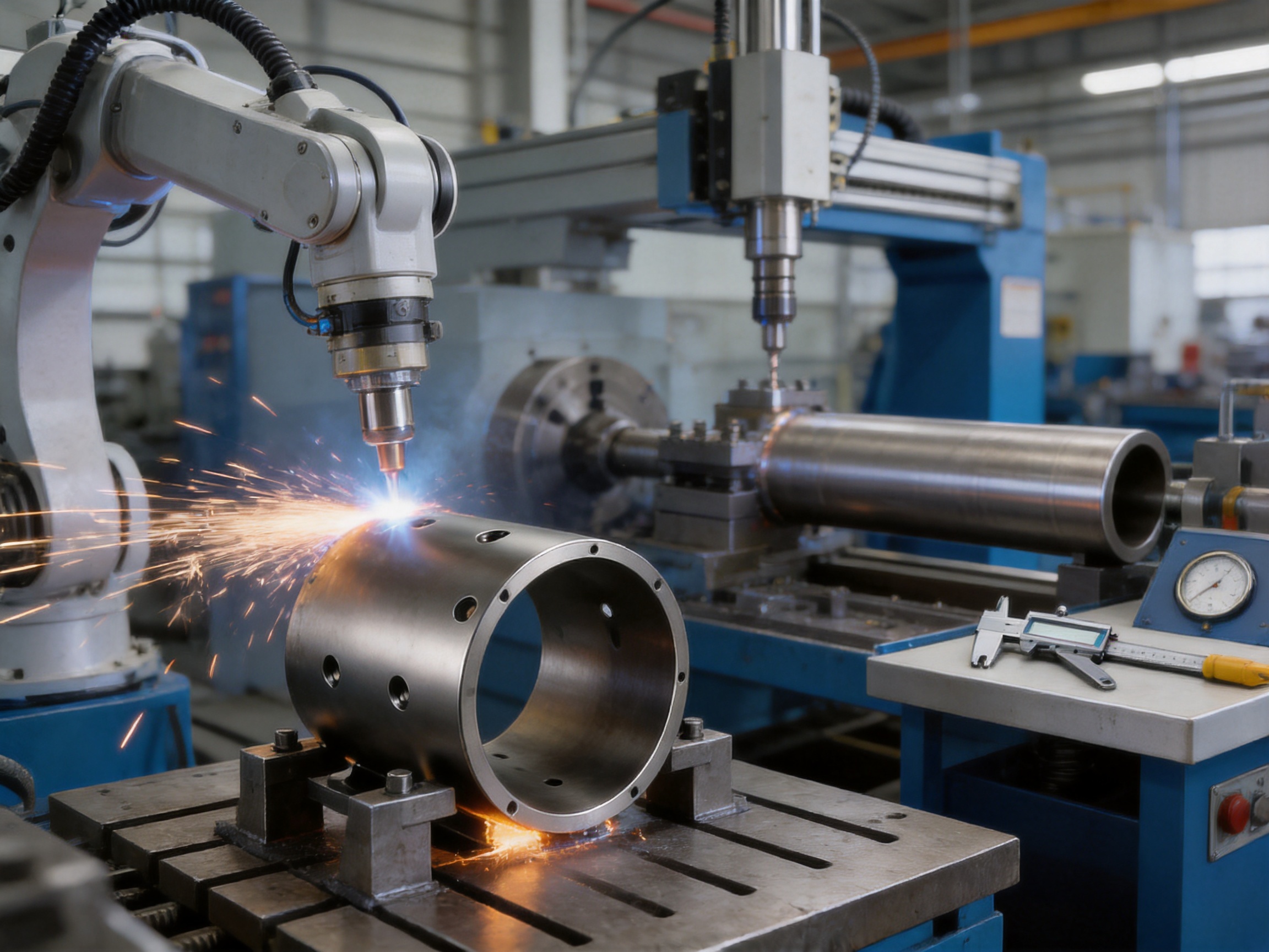
The manufacturer describes its operations as including stamping lines, automated welding equipment, machining facilities, and inspection instruments. Automated or semi-automated welding can provide repeatable process control when the fixture, welding parameters, and component preparation are properly managed. Machining equipment supports the creation of accurate interfaces, while inspection instruments provide feedback on the finished product.
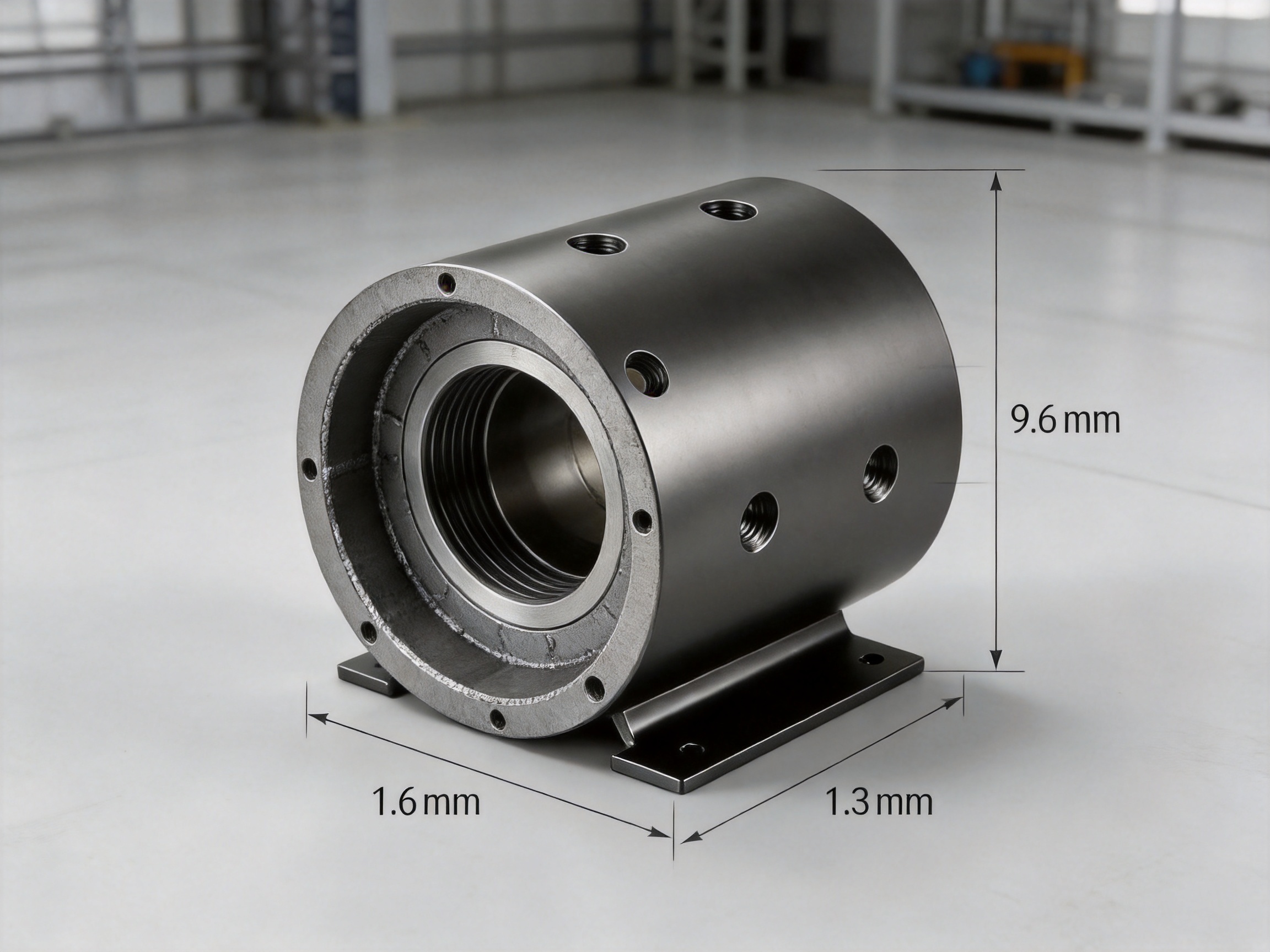
Advantages over Generic and Light-Duty Alternatives
Greater Structural Confidence
A generic thin-wall tube may provide a basic enclosure, but it may not offer the same resistance to external impact, local deformation, or mounting stress. The 9.6 mm wall thickness gives this product a more substantial structural profile. For mobile equipment, this can be a meaningful advantage when the housing is exposed to vibration and changing loads.
More Complete Mounting Configuration
Many basic housings require customers to fabricate a separate support structure and add holes during assembly. This product includes a welded base and multiple threaded interfaces as part of the design. The more complete configuration can reduce fabrication steps at the customer’s facility and support a cleaner, more repeatable installation.
Improved Modularity
The eight side screw holes and eight end-face threaded holes provide connection points for covers, guards, brackets, and flanges. This is more flexible than a housing with only a smooth tube wall or a limited number of mounting points. The interfaces can help customers adapt the housing to different motor-system layouts while preserving the main body design.
Better Suitability for Mobile Machinery
Some motor housings are developed primarily for indoor stationary equipment. Their design may not account for continuous vibration, transport shock, or the dynamic loads associated with lifting equipment. This product is specifically positioned for aerial work platforms and related special vehicles, making its heavy-wall body and welded base relevant to mobile applications.
Integrated Manufacturing Capability
A supplier that can manage steel processing, welding, machining, surface treatment, and inspection within an integrated production system may provide stronger control over the complete component. This can help reduce coordination problems among multiple suppliers and support more consistent production when the product enters volume manufacturing.
Support for Customization
Motor housing requirements often vary according to motor size, installation direction, fastener standards, cable routing, coating, and equipment layout. A manufacturer with engineering and process capabilities across several production stages can evaluate customization requests more effectively. The current product provides a defined starting platform that can be adapted when the customer requires changes.
Supplier Manufacturing Strengths
Jiangsu Yufeng Electric Co., Ltd. is described as a professional manufacturer specializing in motor housings and related component production. Its stated capabilities include research and development, stamping, welding assembly, machining, surface treatment, and finished product delivery. This broad scope is important because a motor housing is rarely successful through one operation alone.
The company reports approximately 40 years of experience in motor housing manufacturing, service to more than 50 customers, and annual production capacity exceeding 5 million units. These figures indicate experience with repeated production, process organization, and customer-oriented delivery. They should be considered together with the customer’s required audit, quality documentation, and product validation procedures.
The company also describes an engineering team with an average of more than 20 years of experience. Experienced engineers can contribute to drawing review, process design, welding sequence planning, fixture development, tolerance analysis, and production troubleshooting. Such support is valuable when a customer is moving from a prototype housing to a stable mass-production design.
Applications served by the company reportedly include household appliances, industrial drives, new energy vehicles, and special equipment. This range suggests exposure to different requirements involving appearance, dimensional consistency, structural durability, production efficiency, and surface treatment. Experience across several industries can help a supplier identify process risks and recommend practical manufacturing solutions.
For international customers, supplier strength also includes communication and project management. Clear drawing confirmation, sample approval, inspection reporting, packaging planning, and delivery coordination are essential. A technically capable housing manufacturer must be able to convert customer requirements into controlled production documents and maintain consistency throughout the order cycle.
Quality Considerations for Customers
Before ordering, customers should confirm the complete technical drawing rather than relying only on the headline dimensions. The 123.8 mm inner diameter and 166 mm height define important product characteristics, but tolerances, concentricity, end-face flatness, hole positions, thread specifications, base dimensions, and surface finish must also be agreed.
The customer should provide information about the motor to be installed, including motor mass, operating speed, torque, vibration level, thermal behavior, shaft arrangement, bearing support, cable orientation, and expected duty cycle. This information helps determine whether the housing is suitable for the complete motor assembly.
Mounting loads should also be reviewed. Aerial work platforms and special vehicles can generate dynamic forces that vary with travel speed, surface conditions, lifting height, and load distribution. The housing, welds, fasteners, and supporting frame should be evaluated as one system. The product’s heavy-wall structure is advantageous, but the final allowable load must be established through engineering analysis and testing.
Environmental requirements should be defined before surface treatment is selected. Indoor industrial equipment may require a different finish from a vehicle exposed to rain, road salt, mud, cleaning chemicals, or coastal air. Customers should specify corrosion expectations, coating thickness, color, masking areas, and any grounding or electrical-continuity requirements.
Inspection documentation may include material certificates, dimensional inspection reports, weld inspection records, thread gauges, surface-treatment records, and final product inspection results. The specific documentation package should match the customer’s quality system and the criticality of the motor application.
Installation and Service Recommendations
Before installation, the housing should be checked for transport damage, contamination, thread blockage, burrs, coating defects, and dimensional conformity. The mounting frame should be clean and sufficiently flat. The base should not be forced into position using excessive bolt tightening because this may distort the housing or create unwanted stress.
Fasteners should match the specified thread, strength class, length, and corrosion-protection requirements. Thread engagement should be sufficient for the expected loads, and tightening torque should follow the final assembly drawing or engineering standard. Where the equipment is subject to continuous vibration, an appropriate locking method may be required.
The motor should be inserted and aligned without impact loading the housing or using the housing as an unintended lifting point. The relationship between the motor shaft, end cover, flange, coupling, and driven equipment should be checked carefully. Misalignment can produce vibration and bearing loads even when the housing itself is structurally sound.
Side screw holes should be used only for components whose mass and dynamic loads are appropriate for the designated interface. Protective covers and auxiliary brackets should not obstruct ventilation, drainage, cable routing, or maintenance access. End-face threaded holes should be kept clean and should not be over-tightened beyond the approved assembly requirements.
During service, operators should inspect the base weld area, mounting fasteners, side attachments, end covers, and visible surfaces for cracks, looseness, corrosion, or deformation. Inspection frequency should reflect the operating environment and duty cycle. If the housing is involved in a collision, severe impact, or abnormal vibration event, it should be inspected before the equipment returns to service.
Customization and Project Development
The standard product provides a useful platform for customers who require an inner diameter of 123.8 mm, a height of 166 mm, a 9.6 mm wall, and the stated interface arrangement. Some projects may require changes to the base shape, hole pattern, thread specification, end-face geometry, surface treatment, or material requirement.
Customization should begin with a technical review. Customers should submit drawings or three-dimensional models showing the motor envelope, mounting direction, load conditions, cable routing, adjacent components, and environmental requirements. The manufacturer can then assess forming, welding, machining, fixture, inspection, and production-volume considerations.
Prototype production is valuable when the housing is part of a new motor or equipment platform. A prototype can verify insertion clearance, base alignment, end-cover fit, cable access, vibration behavior, and service procedures. After testing, design changes can be incorporated before mass production begins.
For large-volume programs, process validation should establish repeatable manufacturing conditions. This may include first-article inspection, fixture validation, welding parameter confirmation, capability studies for critical dimensions, sample testing, and an agreed inspection plan. The goal is to ensure that the production housing performs consistently rather than relying only on the quality of a single sample.
Because the company offers multiple in-house processes, it can potentially support customization from raw steel preparation through finished surface treatment. This can simplify project communication and allow changes to be evaluated across the complete production route. Customers should confirm the exact available process, tolerance, testing, and certification requirements for each project.
Purchasing and Evaluation Checklist
When comparing this product with competing motor housings, buyers should evaluate the complete value rather than comparing only material price or external dimensions. A lower-priced tube may require separate brackets, additional drilling, manual welding, surface treatment, and alignment work. These additional operations can increase total cost and introduce more quality risks.
The following factors should be considered during supplier evaluation:
- Compatibility of the 123.8 mm inner diameter with the selected motor.
- Suitability of the 166 mm height for the complete motor assembly.
- Structural requirements associated with the 9.6 mm wall thickness.
- Base geometry, weld design, and mounting-hole arrangement.
- Number and location of side and end-face interfaces.
- Material traceability and confirmation of the 20# steel specification.
- Dimensional tolerances and inspection methods.
- Welding process control and weld inspection capability.
- Machining accuracy for functional surfaces and threads.
- Surface treatment and corrosion-resistance requirements.
- Prototype, customization, and engineering-support capability.
- Production capacity, delivery planning, and quality documentation.
A supplier should be able to clarify which dimensions are controlled during tube processing, which are established after welding, and which are inspected at final release. This information helps customers understand the manufacturing route and identify the dimensions most important to system performance.
Packaging should also be discussed. Threaded holes and machined surfaces must be protected against impact and contamination during transport. The housing should be packed in a way that prevents the welded base from bending and prevents parts from contacting one another in a manner that could damage the coating or finished surfaces.
Environmental and Safety Considerations
Steel motor housings can provide durable mechanical protection, but the final assembly must be designed for its complete environment. If the housing is installed outdoors, corrosion protection is important. If it is exposed to water spray, mud, dust, or cleaning chemicals, the housing and attached covers should be evaluated for sealing, drainage, and material compatibility.
The housing itself does not automatically define the ingress-protection rating of the complete motor. The end covers, seals, cable entries, fasteners, and assembly joints all contribute to environmental protection. Customers should therefore validate the completed motor and housing assembly according to the applicable equipment requirements.
Electrical grounding and bonding should be considered where the housing is part of a motor system. Steel is electrically conductive, but coating, mounting interfaces, and fastener conditions may affect electrical continuity. The final grounding method must be defined by the equipment designer and verified during assembly.
Safety also depends on correct installation. The welded base and threaded interfaces support secure mounting, but they must be used within their design intent. Overloading the side holes, using incorrect fasteners, ignoring alignment, or operating the machine after visible structural damage can compromise safety. Proper installation, inspection, and maintenance remain essential.
Overall Product Value
The Inner Diameter 123 Heavy-Wall Motor Housing With Base offers a practical combination of strength, compactness, and installation flexibility. Its 123.8 mm inner diameter and 166 mm height support a defined motor envelope, while the 9.6 mm wall provides a substantial structural section. The welded base gives the complete motor unit a stable mounting foundation, and the multiple threaded interfaces make it easier to attach covers, flanges, guards, and auxiliary components.
These features distinguish the product from a basic steel tube or a light-duty motor enclosure. The design is intended for equipment where vibration, impact, changing loads, and limited installation space must all be considered. Aerial work platforms, scissor lifts, mobile cranes, service vehicles, and other special machines can benefit from a housing that is designed as an integrated structural component.
The product is further supported by the manufacturing capabilities described by Jiangsu Yufeng Electric Co., Ltd. Its integrated approach includes steel processing, stamping, welding assembly, machining, surface treatment, and inspection. Experience in motor housing production, an established engineering team, reported large-scale production capacity, and service across several industries provide a strong foundation for both standard supply and customized development.
Customers selecting a motor housing should evaluate the complete system, including motor dimensions, dynamic loads, mounting structure, environmental conditions, tolerances, surface treatment, and service requirements. When these factors are confirmed through engineering review and product validation, the heavy-wall housing can provide a durable and adaptable foundation for demanding motor assemblies.
Questions and Answers
What is the inner diameter of the motor housing?
The specified inner diameter is 123.8 mm. Customers should compare this dimension with the motor body diameter, required clearance, insulation or protective elements, and any internal fitting requirements before ordering.
What is the height of the housing?
The housing height is 166 mm. This dimension should be checked against the complete axial length of the motor assembly, including end covers, bearing structures, shaft extensions, and required installation clearances.
What is the wall thickness?
The wall thickness is 9.6 mm. This heavy-wall construction is intended to provide improved structural rigidity and resistance to deformation compared with lighter-duty tube designs.
What material is used?
The material specification is 20# steel. The customer should confirm the applicable material standard, mechanical requirements, chemical composition, inspection documentation, and surface-treatment needs during technical approval.
Does the product include a mounting base?
Yes. The product includes a welded steel base. The base is designed to provide firm mounting support for the motor housing and complete motor unit when integrated into suitable equipment structures.
How many side screw holes are provided?
Eight screw holes are provided on the housing side. They can support auxiliary components, protective covers, brackets, or other customer-approved attachments.
How many threaded holes are located on the end faces?
Each end face includes four threaded holes, providing eight end-face threaded interfaces in total. These interfaces are intended for accurate positioning and fastening of end covers, flanges, or related components.
Which equipment is this housing designed for?
The product is specifically developed for aerial work platform motors. It is also suitable for consideration in scissor lifts, mobile cranes, service vehicles, and other special equipment where structural strength and installation flexibility are important.
Is the housing suitable for every motor with a 123.8 mm diameter?
Not automatically. The inner diameter is only one compatibility factor. Customers should also verify motor length, shaft arrangement, bearing support, end-cover geometry, mounting loads, operating temperature, vibration, cable routing, and required clearances.
Can the housing be customized?
Customization may be possible depending on the required change and production conditions. Potential subjects for review include base geometry, hole positions, thread specifications, dimensions, machining requirements, and surface treatment. A drawing or three-dimensional model should be provided for engineering evaluation.
Does the housing itself define the motor’s environmental protection rating?
No. The protection level of the complete motor assembly also depends on end covers, seals, cable entries, joints, coatings, and assembly methods. Environmental validation should be conducted on the completed product.
What should be checked before installation?
Customers should check the inner diameter, height, mounting-base condition, hole positions, thread cleanliness, machined surfaces, weld appearance, coating condition, and transport damage. The supporting frame should also be clean, flat, and suitable for the expected loads.
Why is integrated manufacturing useful for this product?
Integrated manufacturing can coordinate steel processing, welding, machining, surface treatment, and inspection within one production system. This may improve process consistency, simplify communication, support customization, and reduce the coordination risks associated with multiple independent suppliers.
What information should be included in an inquiry?
An inquiry should include the motor drawing, housing dimensions, interface requirements, material standard, operating environment, expected production quantity, surface-treatment requirements, inspection documentation, packaging needs, and delivery schedule. Load and vibration information is also valuable for special-equipment applications.
References
1. Product specification supplied for the Inner Diameter 123 Heavy-Wall Motor Housing With Base.
2. Product information supplied for the steel tube motor housing, including dimensions, material specification, hole arrangement, and application scope.
3. Jiangsu Yufeng Electric Co., Ltd. company profile and stated manufacturing capabilities.
4. General engineering principles for welded steel structures, motor mounting, dimensional control, and vibration-resistant equipment design.
5. General quality-control practices for steel fabrication, welding assembly, machining, surface treatment, and industrial component inspection.

 Previous