

 English
 Español
Content
- 1 Product Overview
- 2 Structural Design and Functional Integration
- 3 Advantages of a 125 mm Steel Motor Housing
- 4 Surface Protection System
- 5 Manufacturing Process and Quality Control
- 6 Advantages Over Basic or Less Integrated Alternatives
- 7 Application Possibilities
- 8 Customization and Engineering Support
- 9 Company Manufacturing Strengths
- 10 Installation and Integration Considerations
- 11 Quality, Reliability, and Lifecycle Value
- 12 Recommended Purchasing and Technical Review Checklist
- 13 Frequently Asked Questions
- 13.1 What is the internal diameter of this motor housing?
- 13.2 What is the overall height?
- 13.3 What material can be used?
- 13.4 Why is the wall thickness 2 mm?
- 13.5 Does the housing include a mounting base?
- 13.6 How many welded studs are included?
- 13.7 What are the benefits of welded studs?
- 13.8 What surface treatment does the product use?
- 13.9 Can the housing resist salt spray?
- 13.10 Is the product suitable for outdoor applications?
- 13.11 Can the housing be customized?
- 13.12 What manufacturing capabilities does the supplier provide?
- 13.13 What industries does the manufacturer serve?
- 13.14 How should customers begin a project?
- 14 Conclusion
- 15 References
- 16 Product: Inner Diameter 125 Steel Motor Housing With Base and nuts
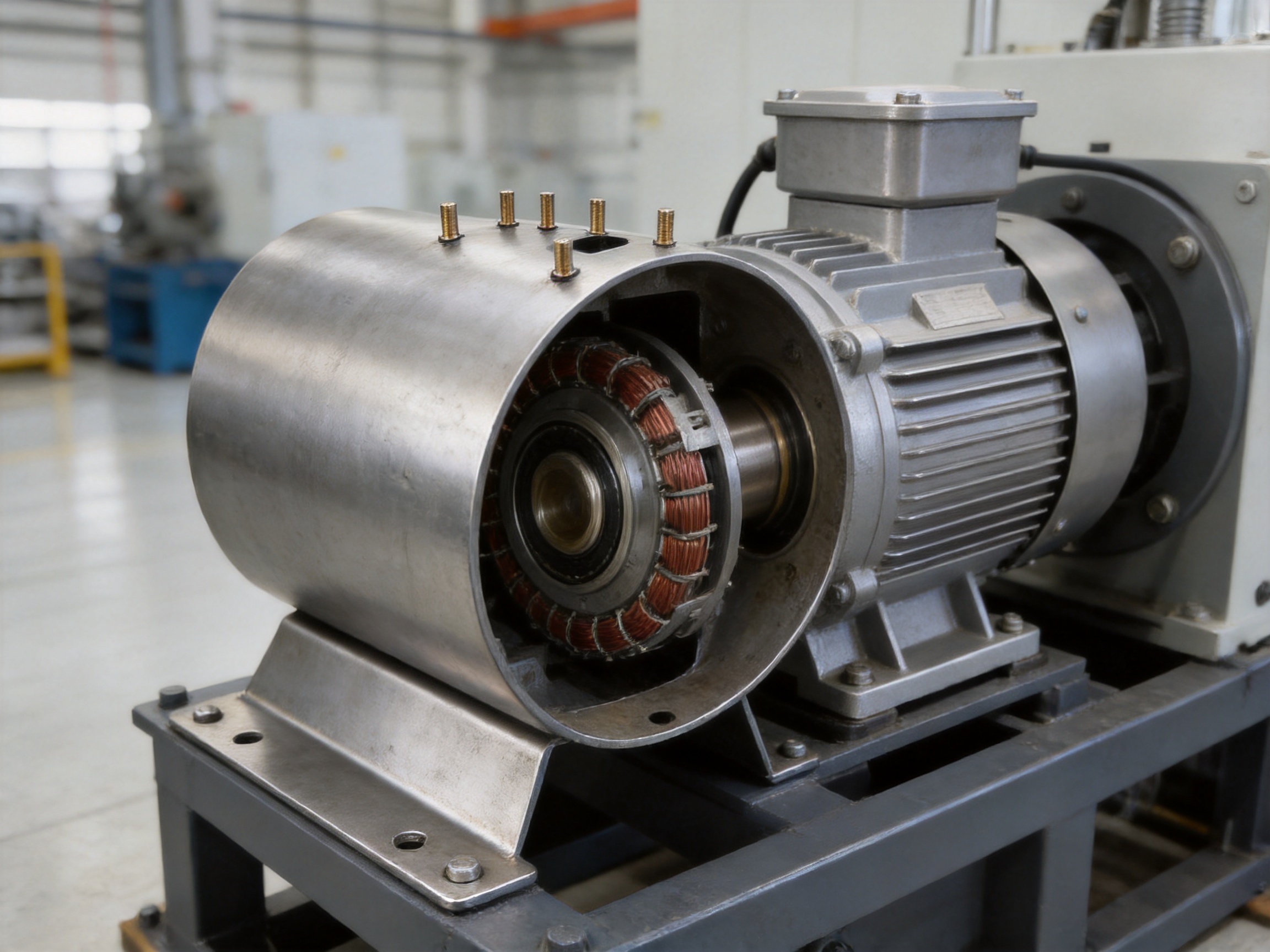
Motor housings are essential structural components in electric motors. They protect internal electrical and mechanical parts, support accurate alignment, help dissipate heat, and provide a stable interface between the motor and the equipment in which it operates. A well-designed housing must withstand vibration, impact, torque, assembly loads, environmental exposure, and long periods of continuous operation. It must also be manufactured consistently enough to maintain dimensional accuracy across large production volumes.
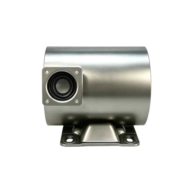
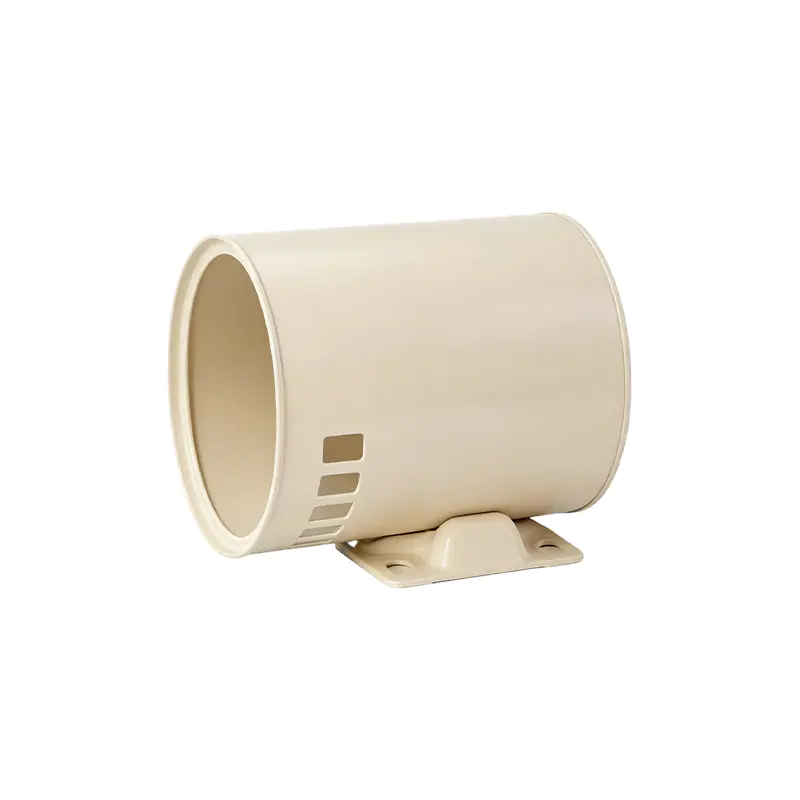
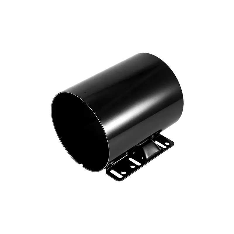
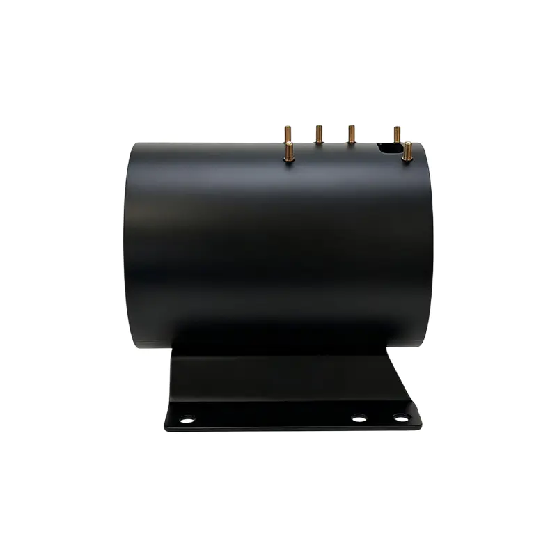
The Inner Diameter 125 Steel Motor Housing with Base and Nuts is designed for applications requiring a compact, reinforced, and corrosion-resistant steel enclosure. Identified as ID125005, this housing combines a nominal inner diameter of 125 mm with a height of 176 mm and a 2 mm wall structure. Its configuration includes a welded bottom base and six welded studs, providing a practical solution for motor assembly, external bracket installation, and equipment integration.
Unlike a basic cylindrical shell, this product is engineered as a functional structural assembly. Its welded base supports stable mounting, its studs simplify connection work, and its electrophoretic coating plus powder-coating system provides enhanced protection against corrosion. These features make the housing suitable for demanding motor applications in household appliances, industrial drives, new energy equipment, special machinery, and other environments where reliability and repeatable manufacturing are important.
Product Overview
The housing is manufactured from SPCC, ST12, or DC01 steel specifications, depending on project requirements and customer confirmation. These materials are commonly used in formed steel components because they offer suitable formability, strength, weldability, and consistency for motor housing production. The 2 mm wall thickness provides a balance between structural rigidity and overall weight, allowing the housing to remain compact without becoming unnecessarily heavy.
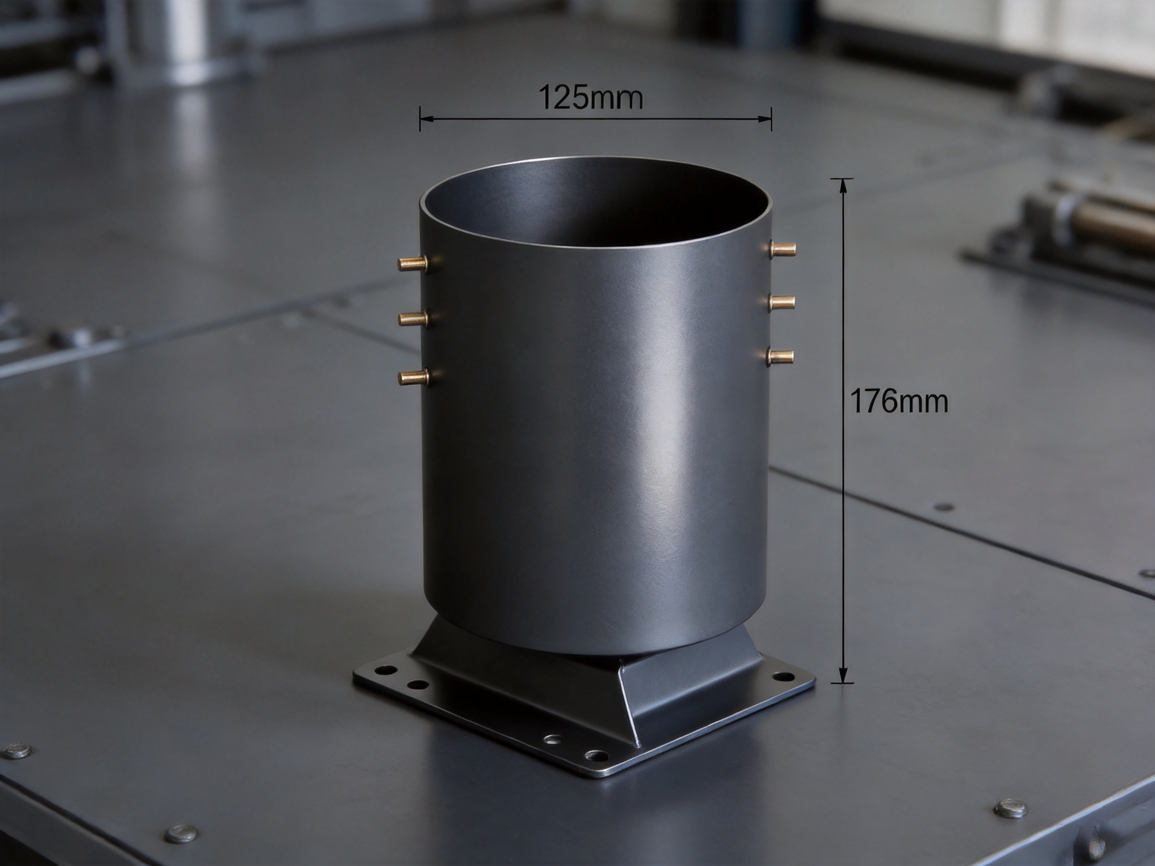
The stated internal diameter is 125.3 mm, while the product is commercially identified as a 125 mm inner-diameter motor housing. The housing height is 176 mm, and the base center distance is 88.9 mm. These dimensions provide an essential foundation for evaluating compatibility with a motor stator, end-shield arrangement, mounting structure, and related components.
| Item | Specification | Engineering Significance |
|---|---|---|
| Product identification | ID125005 | Supports product identification and project communication |
| Housing type | Steel motor housing with welded base and studs | Combines enclosure, support, and attachment functions |
| Inner diameter | 125.3 mm | Defines the primary internal fit and component clearance |
| Height | 176 mm | Determines axial installation space and package dimensions |
| Wall thickness | 2 mm | Provides structural support while limiting unnecessary weight |
| Material specification | SPCC, ST12, or DC01 | Offers suitable forming and welding characteristics |
| Base center distance | 88.9 mm | Supports alignment with the customer’s mounting structure |
| Surface treatment | Electrophoretic coating plus powder coating | Improves corrosion, moisture, impact, and aging resistance |
| Additional features | Welded base and six welded studs | Reduces secondary drilling, tapping, and mounting operations |
Dimensions shown in the table should be verified against the customer’s approved drawings and application requirements before production. Motor housings often interface with multiple precision components, so details such as roundness, concentricity, flatness, hole position, stud location, coating thickness, and assembly clearance should be included in the final technical specification.
Structural Design and Functional Integration
The primary advantage of this housing is that it integrates several structural functions into one manufactured component. The cylindrical body provides the motor enclosure, the welded bottom base offers a stable support interface, and the six welded studs create connection points for external components or mounting brackets. This integrated design can reduce the number of separate parts required in the final motor assembly.
A motor housing must do more than surround the motor. It must maintain its shape under clamping forces, transportation loads, vibration, and operating torque. If the housing deforms, even slightly, it may affect the alignment of internal parts or create uneven contact between mating components. A 2 mm steel wall, when properly formed and reinforced by the overall assembly design, can provide a useful combination of stiffness, manufacturability, and weight control.
The welded base is especially important in applications where the motor is fixed to a larger machine. A weak or poorly aligned base may loosen during operation, particularly when the equipment is exposed to vibration or repeated starts and stops. By welding the base directly to the housing, the design creates a permanent connection rather than relying only on removable fasteners or localized sheet-metal tabs.
The product description specifies that the base is welded using high-standard welding technology and is designed to withstand tensile forces exceeding 2000 kg of force under stated test or design conditions. Actual performance depends on weld geometry, material condition, loading direction, fixture accuracy, weld quality, and the customer’s application. Nevertheless, the specification demonstrates that the base is intended for high-load service rather than light-duty enclosure use.
The six welded studs further improve functional integration. Instead of requiring the customer to drill holes, tap threads, or install separate fasteners into the housing wall, the studs are positioned during manufacturing and permanently attached. This approach can save assembly time and reduce the risk of incorrectly located holes, damaged coatings, or inconsistent thread quality caused by secondary processing.
Inner Diameter 125 Steel Motor Housing With Base and nuts
Advantages of a 125 mm Steel Motor Housing
Balanced Strength and Weight
The 2 mm steel wall is designed to provide a practical balance between rigidity and material efficiency. A housing that is too thin may be vulnerable to denting, vibration, and deformation during handling or operation. A housing that is unnecessarily thick can increase weight, material cost, forming force, and transportation expenses. The selected wall thickness supports a compact product architecture while preserving the inherent strength of steel.
Steel also offers predictable mechanical behavior and broad availability. Compared with certain lightweight materials, steel can provide strong resistance to localized impact and fastening loads. It is also compatible with established stamping, forming, welding, machining, and coating processes. This makes it suitable for customers that require repeatable production and stable supply over long product life cycles.
Reinforced Mounting Capability
The welded base is a major differentiator compared with plain cylindrical motor shells. A simple shell may require an additional mounting bracket or a separate support plate. That can increase the part count, assembly time, and tolerance stack-up. The integrated base in this product provides a direct mounting interface and can simplify the customer’s overall motor or equipment architecture.
The base center distance of 88.9 mm provides a defined reference for mounting layout. This dimension should be coordinated with the motor frame, machine bracket, and installation bolts. When the base is produced consistently from controlled tooling and welding fixtures, the customer can achieve more repeatable assembly positioning from one unit to the next.
Preinstalled Welded Studs
Six welded studs are supplied as part of the housing structure. These studs can be used to attach external covers, brackets, electrical protection components, cable-management elements, or other motor-related parts, subject to the approved design. Their inclusion eliminates or reduces operations such as drilling, tapping, nut insertion, and manual positioning.
Preinstalled studs also help preserve the integrity of the coated housing. Secondary drilling after coating can expose bare steel and create a potential corrosion initiation point if the area is not properly repaired. A factory-installed stud can be welded before surface treatment, allowing the coating system to cover the housing and welded areas in a more controlled manner.
Compact Geometry for Equipment Integration
With a 125.3 mm internal diameter and a 176 mm height, the housing is suitable for compact motor designs where enclosure space is limited. The dimensions allow engineers to evaluate the product against a specific stator and rotor package without adopting an unnecessarily large frame. Compact geometry can support reduced machine size, easier equipment integration, and more efficient use of installation space.
However, compactness must always be evaluated together with thermal, electrical, and mechanical requirements. The internal clearance should be checked against stator insulation, winding overhang, rotor movement, bearing arrangements, and any required air gap or ventilation features. The housing should be selected as part of a complete motor design rather than evaluated only by its nominal diameter.
Surface Protection System
The housing uses a dual surface treatment consisting of electrophoretic coating, commonly called ED coating, followed by powder coating. This two-stage system is intended to provide stronger and more comprehensive protection than a single conventional finish. The ED layer is designed to reach complex surfaces and provide adhesion, while the powder topcoat contributes additional resistance to impact, aging, moisture, and environmental exposure.
Electrophoretic Coating
Electrophoretic coating uses an electrically assisted deposition process to apply a protective coating over conductive metal surfaces. The process can provide relatively uniform coverage, including areas that may be difficult to coat consistently using simple spray methods. This is valuable for motor housings because corrosion can begin in less visible areas such as corners, welded joints, recessed surfaces, and the inner edges of mounting features.
Good ED coating performance depends on pretreatment, surface cleanliness, bath control, electrical parameters, rinsing, curing, and process monitoring. Before coating, oil, scale, dust, and welding residue should be removed. Proper pretreatment improves adhesion and helps the coating system resist underfilm corrosion when the housing is exposed to humidity or salt contamination.
Powder-Coating Top Layer
The powder-coating layer provides an additional barrier and can improve the housing’s visible finish. Powder coatings are widely used for industrial metal components because they can offer good resistance to abrasion, impact, weathering, and general handling damage. The selected powder formulation should match the intended environment, temperature range, color requirement, and performance specification.
The topcoat also provides an opportunity to standardize product appearance across production batches. A consistent appearance can be important for equipment manufacturers that place finished motors into visible appliances, industrial modules, or branded machinery. Color, gloss, texture, and coating thickness should be defined in the customer’s approved specification.
Salt Spray and Environmental Resistance
The product description states that the dual coating system can meet at least 2000 hours of salt spray test requirements under the applicable test conditions. Salt spray testing is a comparative accelerated corrosion test, and the result should be interpreted together with the test standard, specimen preparation, scribe method, coating thickness, exposure environment, and evaluation criteria.
A long salt spray result does not mean that the housing is immune to corrosion in every real-world environment. Actual service performance depends on temperature, humidity, chemicals, abrasion, water retention, galvanic contact, installation orientation, and maintenance. Nevertheless, a coating system designed for a 2000-hour requirement indicates a high level of attention to corrosion protection and makes the housing a strong candidate for harsh industrial or humid applications.
Manufacturing Process and Quality Control
The performance of a motor housing depends not only on its design but also on the stability of the manufacturing process. Jiangsu Yufeng Electric Co., Ltd. operates an integrated production system covering stamping, welding assembly, machining, surface treatment, and inspection. This full-process capability is valuable because it allows the major manufacturing stages to be coordinated under one production organization.
Steel Material Preparation
Production begins with steel material that conforms to the approved specification, such as SPCC, ST12, or DC01. Material verification may include checking thickness, surface condition, mechanical characteristics, chemical documentation, and supplier records. Consistent incoming material helps reduce variation during forming and welding.
Material preparation also includes coil or sheet handling, blank development, cutting, and identification. The blank dimensions must be controlled carefully because they influence the final cylindrical diameter, height, seam condition, and material utilization. Proper nesting and process planning can reduce scrap and improve production efficiency, particularly for high-volume programs.
Stamping and Forming
Stamping and forming equipment is used to transform flat steel into the required housing geometry. Depending on the design, the process may include blanking, deep drawing, rolling, flanging, trimming, piercing, or other forming operations. Tooling must be designed to control springback, prevent wrinkles, avoid excessive thinning, and maintain the required dimensional profile.
For a motor housing, dimensional control is especially important around the inner diameter and end faces. Excessive variation may affect the fit of the stator or end components. The forming process should therefore be supported by suitable gauges, inspection fixtures, and periodic dimensional verification.
Tool maintenance is another important factor. Worn punches, dies, guides, or forming surfaces can gradually change the product shape. A systematic maintenance schedule helps protect consistency and prevents small dimensional changes from becoming assembly problems during mass production.
Welding Assembly
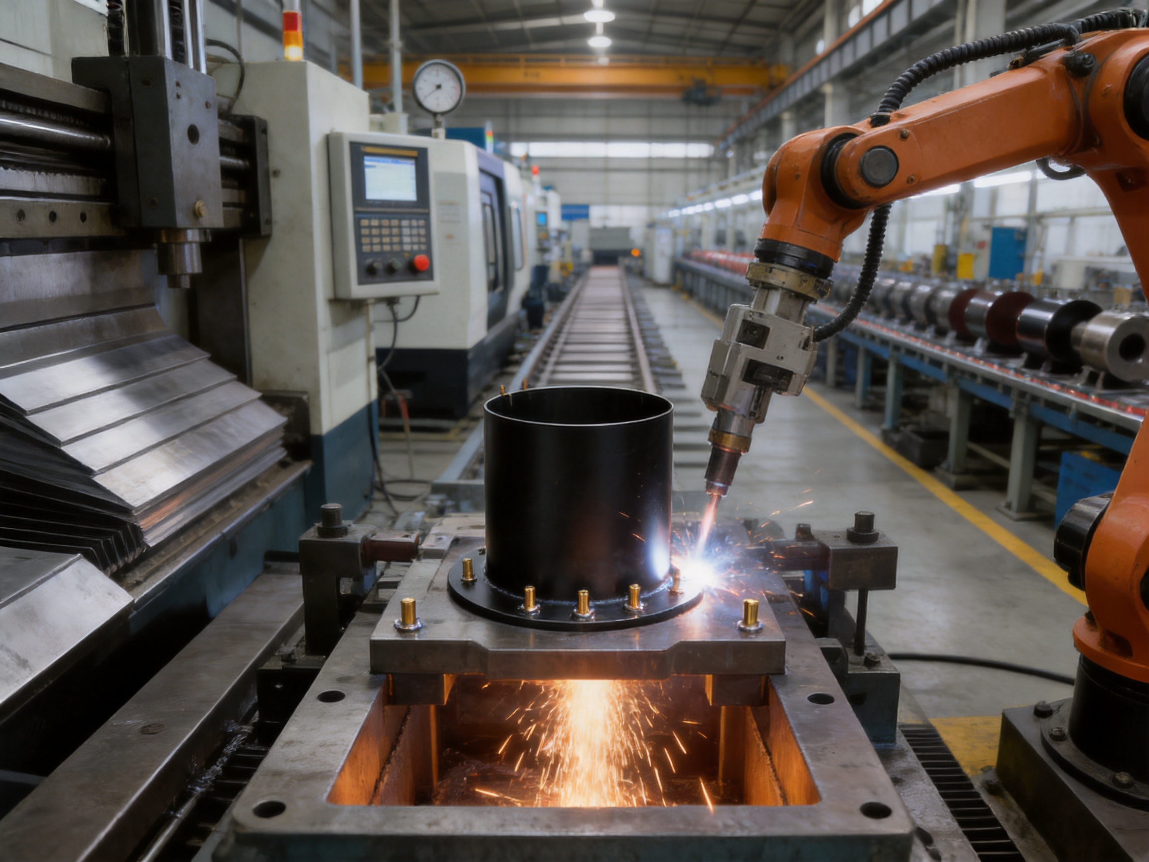
After forming, the housing body is joined with the base and welded studs. Welding fixtures help position these parts accurately before the weld is applied. A stable fixture is essential for controlling base location, center distance, stud spacing, angular orientation, and housing distortion.
Welding parameters may include current, voltage, time, pressure, electrode condition, shielding conditions, and sequence. The appropriate parameters depend on the material, joint design, welding method, and production equipment. The objective is to achieve a strong, repeatable joint with suitable penetration and minimal distortion.
Weld quality can be evaluated through visual inspection, dimensional inspection, destructive testing, pull testing, torque testing, or other methods defined by the customer and the product risk level. For the base, tensile or load testing can help verify that the welded support meets the specified strength requirement. For welded studs, pull-out resistance, thread integrity, perpendicularity, and positional accuracy may be checked.
Automated or semi-automated welding can improve repeatability compared with entirely manual operations. Automation does not eliminate the need for skilled technicians, however. Operators and engineers must still manage fixture condition, electrode wear, parameter control, weld spatter, part cleanliness, and corrective action when abnormalities occur.
Machining and Secondary Operations
Some motor housing projects require machining after forming or welding. Machining may be used to achieve precise end-face flatness, critical diameters, bearing-related interfaces, mounting surfaces, or other tolerance requirements. The extent of machining depends on the motor design and the customer’s drawing.
Integrated machining capability allows the manufacturer to coordinate formed geometry with subsequent precision operations. This is useful when a housing requires both sheet-metal forming and accurately machined reference surfaces. It can also reduce the need to transfer semi-finished parts between unrelated suppliers.
Surface Treatment
Before ED coating and powder coating, the housing should undergo appropriate cleaning and pretreatment. Welding residue, oils, dust, and other contaminants can reduce coating adhesion or create surface defects. Pretreatment may include degreasing, rinsing, conversion treatment, drying, and other steps appropriate to the selected coating system.
Process controls should address coating bath condition, electrical settings, oven temperature, curing time, powder application, and film thickness. Coating inspection may include visual checks, thickness measurement, adhesion testing, hardness or impact testing, and corrosion testing. Areas around welds and studs deserve special attention because geometry changes can affect coating coverage.
Final Inspection and Traceability
Final inspection should verify the dimensions and functions that matter most to the customer. Typical checks may include inner diameter, height, base center distance, wall condition, base flatness, stud location, stud condition, weld appearance, coating coverage, and overall appearance.
Traceability can connect the finished housing to its material batch, production date, tooling, welding parameters, coating lot, inspection records, and packaging information. Such records support quality investigations, process improvement, and customer confidence. They are particularly valuable for motor manufacturers operating under strict supplier qualification and production approval systems.
Advantages Over Basic or Less Integrated Alternatives
Many motor housing options are available in the market, including plain steel shells, cast housings, aluminum housings, welded assemblies with separate brackets, and housings that receive only a single paint layer. Each design has its own suitable applications. The key advantage of the ID125005 configuration is the combination of structural steel construction, integrated mounting features, and advanced surface protection.
Compared with a Plain Cylindrical Shell
A plain shell may provide enclosure protection but often requires separate base components and additional attachment hardware. The integrated welded base of this product can simplify the customer’s assembly and reduce the number of components. The six welded studs further extend this advantage by creating ready-to-use connection points.
Fewer separate parts can reduce purchasing complexity, inventory requirements, assembly labor, and tolerance accumulation. It can also reduce the number of interfaces that may loosen under vibration. The exact savings depend on the customer’s motor design and assembly method, but the integrated structure provides a clear opportunity for process simplification.
Compared with Light-Gauge Sheet Metal
Very thin sheet metal can reduce material weight but may be more vulnerable to denting, deformation, handling damage, and local fastener loads. The 2 mm wall thickness provides a more substantial structure while retaining the production benefits of formed steel. For applications exposed to repeated vibration, impact, or heavy mounting loads, this balance may provide greater confidence than an ultra-light shell.
Compared with Uncoated or Single-Coated Steel
Uncoated steel is vulnerable to moisture and oxidation, while a basic single coating may provide less complete protection at edges, corners, and welded areas. The ED-plus-powder system provides two protective layers and is specified for a high salt spray performance target. This makes it more suitable for humid, salty, or corrosive environments than a minimally protected steel housing.
Compared with Some Aluminum Alternatives
Aluminum can offer low weight and good corrosion behavior in certain applications, but steel may be preferred when higher local stiffness, impact resistance, weldability, or cost stability is required. Steel also supports a broad range of stamping and welding processes. The correct choice depends on total motor weight, thermal design, corrosion conditions, production volume, and structural requirements.
Compared with Cast Housings
Cast housings can provide complex geometries and robust structures, but casting often involves different tooling, material, machining, and quality considerations. A formed and welded steel housing can be advantageous when the required shape is suitable for sheet-metal processing and when customers value flexible production, efficient material use, and integrated welded features.
Application Possibilities
The housing is designed for use as part of an electric motor assembly. Its potential application areas include household appliances, industrial drives, new energy vehicles, special equipment, and other motor-powered systems. Final suitability depends on the motor’s electromagnetic design, thermal conditions, rotational speed, vibration level, mounting arrangement, and environmental exposure.
Household Appliances
Household appliance motors often require compact packaging, consistent appearance, corrosion resistance, and economical mass production. A formed steel housing with a protected finish can support these requirements. The integrated base may also simplify installation within appliances where space and assembly time are carefully controlled.
Appliance applications can involve humidity, detergents, temperature cycles, and repeated starts and stops. The coating system should therefore be reviewed against the actual environment, including possible chemical exposure and areas where water may collect. Customer validation should include assembly tests and, where appropriate, endurance testing under representative operating conditions.
Industrial Drives
Industrial motors may experience continuous operation, vibration, dust, oil mist, temperature changes, and significant mounting loads. The reinforced steel design, welded support, and corrosion-resistant finish can provide a suitable foundation for demanding drive applications. The six welded studs may support the installation of guards, cable components, sensors, or other external equipment.
Industrial customers should confirm the required protection class, ventilation arrangement, grounding method, noise limits, and mounting orientation. The housing itself is only one part of the motor system, so its design must be integrated with end covers, seals, fans, terminal boxes, and other components.
New Energy Equipment
New energy systems frequently require compact motors and auxiliary drives installed in challenging environments. Depending on the specific vehicle or equipment platform, a steel housing can offer valuable impact resistance and stable attachment points. The coating system may also help protect against moisture and road-salt exposure when the housing is used in suitable applications.
Automotive and new energy customers typically require extensive validation, documentation, traceability, and process approval. The manufacturer’s integrated capabilities in stamping, welding, machining, finishing, and inspection can support these requirements, subject to the customer’s quality system and project-specific approval process.
Special Equipment
Special equipment manufacturers often need customized dimensions, mounting patterns, welded attachments, and surface finishes. A flexible motor housing supplier can adapt the product structure to suit a specific motor or machine interface. The ID125005 product provides a reference platform for discussions regarding diameter, height, base configuration, stud locations, material, and coating requirements.
Customization and Engineering Support
Motor housing projects frequently begin with a standard concept but require adjustments before mass production. Changes may involve inner diameter, overall height, wall thickness, base dimensions, hole patterns, stud quantity, stud size, coating color, machining allowances, or packaging. Customization should be completed through controlled drawings and engineering review rather than informal dimensional changes.
Jiangsu Yufeng Electric can support customers from product development through mass production. Its engineering team is described as having an average of more than 20 years of experience. Such experience can be useful when reviewing forming feasibility, weld access, distortion risk, coating coverage, assembly tolerances, and production tooling.
Design-for-Manufacturing Review
A design-for-manufacturing review should take place before tooling begins. Engineers can assess whether the proposed diameter and height can be formed reliably, whether the base can be welded without excessive distortion, and whether the studs can be positioned and welded consistently. They can also identify areas where machining or additional reinforcement may be required.
Attention should be given to transitions, sharp corners, weld accessibility, drainage, coating coverage, and inspection access. Smooth transitions can reduce forming stress, while suitable weld spacing can help control heat concentration. Drainage and venting considerations may be important for surface treatment and for preventing liquid retention during service.
Prototype and Sample Validation
Prototype or sample production allows the customer to evaluate physical fit and function before full-scale production. Sample validation may include dimensional checks, assembly trials, base load testing, stud pull testing, coating adhesion evaluation, salt spray exposure, vibration testing, and environmental cycling.
The exact validation plan should reflect the motor’s risk profile. A housing for a low-load indoor application may require a different test program from one installed outdoors or in a high-vibration industrial system. Establishing acceptance criteria in advance helps prevent misunderstandings during project approval.
Production Scale-Up
Once the design is approved, the supplier can move from sample production to pilot runs and mass production. Production scale-up should confirm that tooling, welding fixtures, coating equipment, inspection methods, packaging, and material supply are all ready for the required volume.
The company reports an annual production capacity of more than five million units and experience serving more than 50 customers. This capacity can be valuable for customers seeking a supplier capable of supporting recurring orders rather than only small prototype quantities. Production capacity should still be matched with the specific product mix, delivery schedule, quality requirements, and forecast stability.
Company Manufacturing Strengths
Jiangsu Yufeng Electric Co., Ltd. is a professional manufacturer specializing in motor housings and related production services. Its capabilities cover stamping, welding assembly, machining, surface treatment, and inspection. By combining these processes, the company can manage a housing through multiple stages of production within a coordinated manufacturing system.
The company has approximately 40 years of experience in motor housing manufacturing. Long-term specialization can support accumulated knowledge in tooling design, material behavior, weld control, dimensional management, coating preparation, and customer communication. Experience is particularly important for products that appear simple but require strict control of many interconnected dimensions.
The company’s production scope serves household appliances, industrial drives, new energy vehicles, and special equipment. This range suggests familiarity with different customer expectations, including high-volume production, customized engineering, environmental resistance, and application-specific mounting requirements.
Its equipment base includes stamping lines, automated welding equipment, machining facilities, and inspection instruments. Stamping lines support efficient formed-part production. Automated welding equipment can improve repeatability for bases and studs. Machining facilities can provide precision finishing where required. Inspection instruments support dimensional and process verification.
The manufacturer’s full in-house production model can also improve communication. When forming, welding, machining, and coating are coordinated by one organization, engineering changes can be assessed across the entire process chain. This reduces the possibility that a change beneficial to one operation creates an unexpected problem in another.
Installation and Integration Considerations
Before installing the housing, customers should verify the inner diameter, height, end-face condition, mounting center distance, stud locations, and available internal clearance. The 125.3 mm inner diameter must be compared with the actual outer dimensions of the motor’s internal components, including any required insulation, coating, air gap, and assembly tolerance.
The welded base should be installed on a sufficiently rigid and accurately prepared support surface. Uneven mounting surfaces can introduce stress into the housing and may affect motor alignment. Mounting fasteners should be selected according to the applied load, vibration level, thread engagement, and applicable engineering standards.
Welded studs should not be used beyond their specified load or torque capability. When attaching external components, the customer should consider bracket thickness, fastener type, tightening torque, vibration resistance, and possible galvanic interaction between dissimilar metals. If studs are used for grounding or electrical continuity, the coating and contact design must be reviewed separately.
The coated surface should be protected during assembly. Excessive impact, uncontrolled clamping, or sharp tools may damage the finish. If the coating is scratched, the repair method should follow the approved coating specification. Bare steel exposed during assembly should not be left untreated in a corrosive environment.
Packaging is also important. The housing should be separated or protected so that welded studs, base edges, and coated surfaces do not contact one another in a way that causes abrasion. Packaging materials should be suitable for the transport route, storage duration, humidity conditions, and stacking requirements.
Quality, Reliability, and Lifecycle Value
A reliable motor housing contributes to the reliability of the entire motor assembly. It helps maintain the position of internal components, supports stable installation, protects against environmental exposure, and reduces the possibility of damage during handling. These benefits can lower the likelihood of premature failure and reduce maintenance or replacement costs.
The integrated base and welded studs can also create lifecycle value by reducing assembly operations. Fewer secondary processes mean fewer opportunities for drilling errors, misalignment, loose hardware, coating damage, and inconsistent workmanship. In high-volume production, even a small reduction in assembly time or rework can produce meaningful savings.
Corrosion protection is another lifecycle factor. Rust can affect appearance, reduce structural thickness, interfere with fasteners, and spread beneath coatings. A dual-layer coating system, when correctly applied and maintained, can delay these problems. The specified salt spray performance provides a useful benchmark for supplier qualification and comparative evaluation.
Lifecycle value should be assessed using total cost rather than purchase price alone. Total cost may include tooling, incoming inspection, assembly labor, additional brackets, secondary machining, corrosion treatment, warranty risk, packaging, logistics, and field service. A housing that includes several required features from the factory may provide a lower overall cost even if its unit price is not the lowest available.
Recommended Purchasing and Technical Review Checklist
Customers considering this housing should prepare a technical review covering the motor, machine, environment, and production plan. The following topics can help establish a complete specification.
- Confirm the required inner diameter and allowable dimensional tolerance.
- Confirm the required housing height and end-face configuration.
- Verify the 2 mm wall thickness against structural and thermal requirements.
- Confirm steel grade selection among SPCC, ST12, DC01, or an approved alternative.
- Review the welded base geometry, flatness, thickness, and mounting center distance.
- Confirm the six-stud quantity, size, thread specification, location, and perpendicularity.
- Define weld strength, appearance, inspection, and testing requirements.
- Specify the ED and powder-coating system, color, gloss, thickness, and curing requirements.
- Confirm the salt spray test standard and acceptance criteria.
- Review internal clearances for stator, rotor, insulation, bearings, and wiring.
- Define packaging, labeling, traceability, and delivery requirements.
- Establish sample approval, pilot-run approval, and change-control procedures.
Frequently Asked Questions
What is the internal diameter of this motor housing?
The listed internal diameter is 125.3 mm. The product is commercially described as a 125 mm inner-diameter steel motor housing. Customers should use the controlled drawing and tolerance specification when confirming fit with internal motor components.
What is the overall height?
The stated height is 176 mm. The measurement reference should be confirmed on the approved product drawing, especially if the base or other welded features are included or excluded from the height definition.
What material can be used?
The listed material specifications are SPCC, ST12, and DC01. The final material should be selected according to forming requirements, mechanical performance, welding conditions, coating compatibility, and customer approval.
Why is the wall thickness 2 mm?
The 2 mm wall is intended to balance structural rigidity, impact resistance, forming feasibility, and weight. The correct thickness for a specific motor depends on loading, vibration, internal support, thermal requirements, and customer design standards.
Does the housing include a mounting base?
Yes. The housing includes a high-strength welded bottom base. The stated base center distance is 88.9 mm, which should be checked against the customer’s mounting structure.
How many welded studs are included?
The housing includes six welded studs. Their exact dimensions, thread type, spacing, and allowable load should be confirmed in the product drawing or project specification.
What are the benefits of welded studs?
Welded studs provide ready-made attachment points for external components or mounting brackets. They can reduce the need for drilling, tapping, separate nuts, and additional assembly operations. They can also help preserve the integrity of the finished coating because they are installed before surface treatment.
What surface treatment does the product use?
The housing uses electrophoretic coating followed by powder coating. The ED layer supports coverage and adhesion, while the powder layer adds protection against impact, aging, moisture, and environmental exposure.
Can the housing resist salt spray?
The product description states that the dual coating system can meet at least 2000 hours of salt spray testing under the applicable test conditions. The test standard, evaluation method, coating thickness, and acceptance criteria should be confirmed for each customer project.
Is the product suitable for outdoor applications?
It may be suitable for selected outdoor or harsh-environment applications because of its steel construction and dual-layer coating. However, suitability depends on temperature, humidity, salt exposure, chemicals, abrasion, sealing, drainage, and the complete motor design. Application validation is recommended.
Can the housing be customized?
Customization may be possible for dimensions, base configuration, stud locations, material, machining, coating, and other design requirements. Customized products should be developed through engineering review, drawings, samples, and formal approval.
What manufacturing capabilities does the supplier provide?
The supplier provides integrated capabilities including stamping, welding assembly, machining, surface treatment, and inspection. This supports coordinated production from steel processing to finished motor housing delivery.
What industries does the manufacturer serve?
The company’s products are used in household appliances, industrial drives, new energy vehicles, and special equipment. Final application suitability should be confirmed through technical review and testing.
How should customers begin a project?
Customers should provide the motor housing drawing, internal component dimensions, mounting requirements, environmental conditions, annual volume, surface finish requirements, and quality expectations. The supplier can then review manufacturability, tooling, samples, testing, and production planning.
Conclusion
The Inner Diameter 125 Steel Motor Housing with Base and Nuts is a structurally integrated solution for motor manufacturers and equipment builders requiring more than a simple protective shell. Its 125.3 mm inner diameter, 176 mm height, and 2 mm steel construction provide a compact foundation for motor assembly. The welded base adds stable mounting capability, while six welded studs support efficient attachment of external components.
Its most significant competitive advantages are the combination of reinforced steel construction, integrated welded features, and dual-layer corrosion protection. The ED-plus-powder coating system is specified for at least 2000 hours of salt spray performance under applicable test conditions, offering a strong basis for applications exposed to humidity, salt, and demanding handling environments.
Jiangsu Yufeng Electric’s manufacturing strengths further support the product. With stamping, automated welding, machining, surface treatment, inspection equipment, long-term motor housing experience, and high annual production capacity, the company can support both customized development and repeat mass production. Its engineering resources can help customers move from initial design review to samples, validation, process approval, and delivery.
For the best result, customers should evaluate the housing as part of the complete motor system. Dimensional fit, weld loads, base alignment, stud usage, coating requirements, thermal conditions, vibration, environmental exposure, and packaging should all be confirmed before production approval. When these factors are properly coordinated, this steel motor housing can provide a durable, assembly-efficient, and corrosion-resistant foundation for reliable electric motor applications.
References
1. Product specification information for ID125005, Inner Diameter 125 Steel Motor Housing with Base and Nuts.
2. Material designations and general application information for SPCC, ST12, and DC01 cold-rolled steel grades.
3. General engineering principles for formed-sheet-metal motor housings and welded structural assemblies.
4. General technical guidance for electrophoretic coating and powder-coating systems on steel components.
5. General salt spray corrosion-testing practices for coated metal products.
6. Manufacturing process principles for stamping, welding, machining, surface treatment, and dimensional inspection.

 Previous