

 English
 Español
Content
- 1 Product Overview
- 2 Precision Cylindrical Structure
- 3 Efficient Heat Dissipation Through Axial Airflow
- 4 Three-Point Mounting for Stability and Easier Leveling
- 5 Advantages Compared with Conventional Alternatives
- 6 Material Selection: SPCC, ST12, and DC01
- 7 Advanced Manufacturing Process
- 8 Application Areas
- 9 Design Considerations for Motor Integrators
- 10 Quality, Reliability, and Production Capacity
- 11 Customization and OEM Support
- 12 Recommended Inspection Points
- 13 Installation and Operating Recommendations
- 14 Why Full In-House Production Matters
- 15 Commercial Value for Equipment Manufacturers
- 16 Frequently Asked Questions
- 16.1 What is the inner diameter of the housing?
- 16.2 What is the external diameter?
- 16.3 What is the height of the housing?
- 16.4 What material is used?
- 16.5 How many mounting brackets does the housing have?
- 16.6 What is the bracket bolt-hole center distance?
- 16.7 Why use three mounting points instead of four?
- 16.8 How does the housing support heat dissipation?
- 16.9 Is the housing suitable for continuous operation?
- 16.10 Can the housing be customized?
- 16.11 Which industries can use this motor housing?
- 16.12 What manufacturing capabilities does the supplier provide?
- 16.13 What should customers provide when requesting a quotation?
- 17 Conclusion
- 18 References
- 19 Product: Inner Diameter 140 Steel Motor Housing With Three Brackets
Motor housings are essential structural and functional components in electric motors. They support the stator assembly, protect internal electrical and mechanical parts, guide heat away from the motor, and provide a reliable interface between the motor and the equipment in which it is installed. A well-designed housing must therefore balance dimensional accuracy, mechanical strength, cooling efficiency, installation convenience, corrosion resistance requirements, manufacturability, and cost.
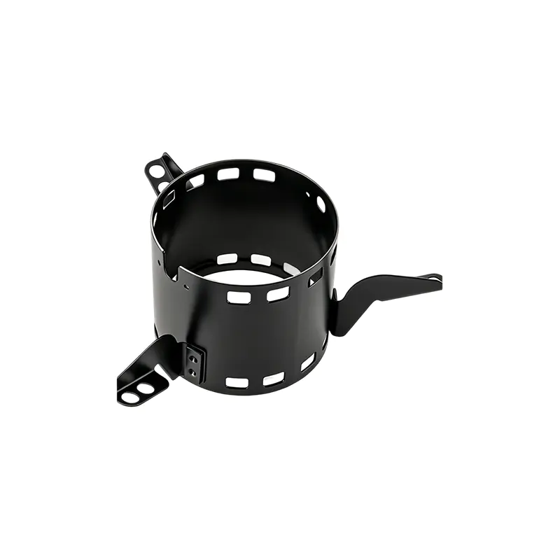
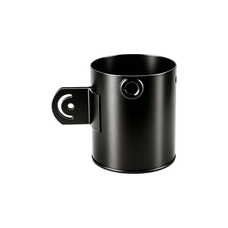
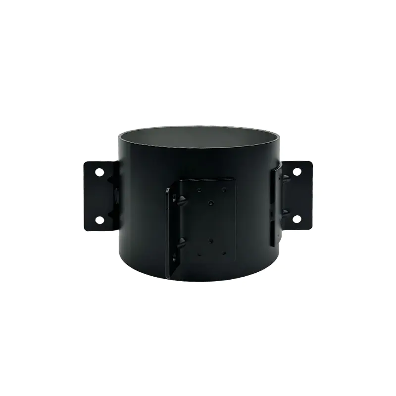
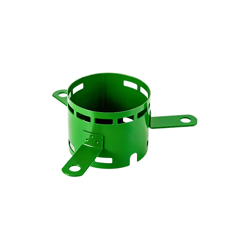
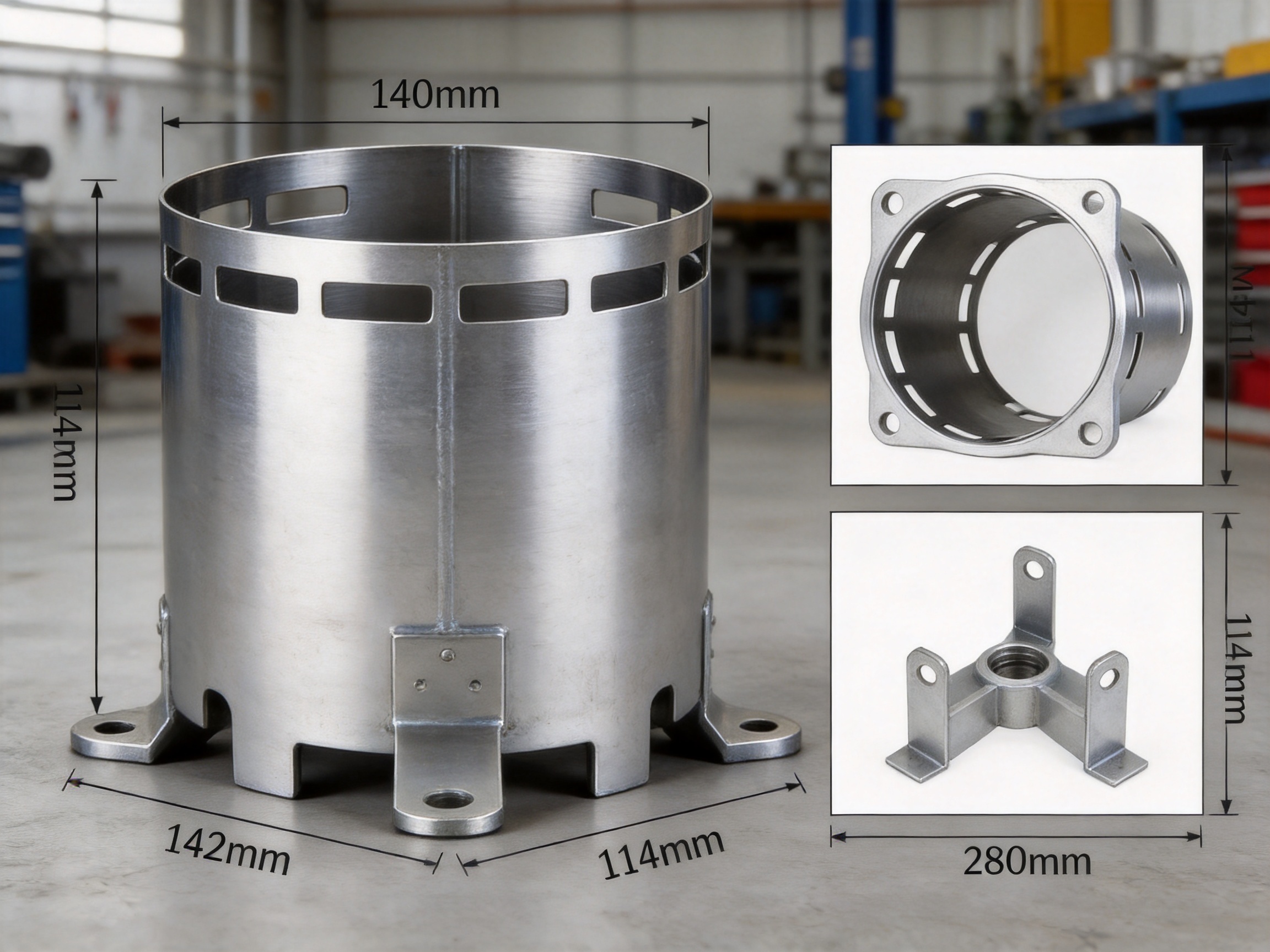
The Inner Diameter 140 Steel Motor Housing with Three Brackets is designed for medium-to-small power motors and compact equipment that require stable support and effective heat dissipation. With an inner diameter of 139.3 mm, an outer diameter of 142.3 mm, a height of 114.3 mm, and a wall thickness of 1.5 mm, this housing uses a thin but capable steel structure to reduce unnecessary weight while maintaining the rigidity required for practical motor applications.
Its design combines a precision-formed cylindrical body, ventilation openings at both ends, and three welded mounting feet. This configuration provides a practical alternative to conventional motor housings that may use heavier walls, less efficient airflow arrangements, or four-point mounting systems that are more difficult to level on uneven surfaces. The result is a housing intended to support stable motor operation, efficient assembly, and dependable service in industrial fans, exhaust systems, agricultural machinery, food processing equipment, packaging machinery, and related applications.
Product Overview
The housing is identified as ID140008 and belongs to the steel motor housing product category. It is manufactured from SPCC, ST12, or DC01-grade steel specifications, depending on the customer’s material requirements and production arrangement. These commonly used low-carbon steel grades are suitable for forming and fabrication processes, making them appropriate for cylindrical motor shells, welded brackets, and other structural components.
The core body has a nominal inner diameter close to 140 mm, with an actual measured inner diameter of 139.3 mm. The 114.3 mm height provides a compact axial profile suitable for motors installed in restricted spaces. A 1.5 mm wall thickness offers a useful balance between material consumption and structural support. The listed outer diameter is 142.3 mm, which corresponds to the nominal wall thickness relationship between the inner and outer surfaces.
Three mounting brackets are welded to the lower portion of the housing. Their bolt-hole center distance is specified as 280 mm. These feet form a three-point support arrangement that helps stabilize the motor and simplifies alignment during installation. Instead of requiring four contact points to sit perfectly on a mounting surface, the three-foot design establishes a geometrically stable support system that is generally easier to level.
| Item | Specification | Functional Significance |
|---|---|---|
| Product code | ID140008 | Identifies the product configuration |
| Housing type | Steel motor housing | Provides structural support and protection for motor components |
| Inner diameter | 139.3 mm | Defines the stator installation space and internal fit |
| Outer diameter | 142.3 mm | Defines the external cylindrical envelope |
| Height | 114.3 mm | Determines the axial housing dimension |
| Wall thickness | 1.5 mm | Balances stiffness, weight, and material use |
| Material specification | SPCC, ST12, or DC01 | Supports forming, welding, and general fabrication |
| Mounting configuration | Three welded brackets | Provides stable three-point support |
| Bracket bolt-hole center distance | 280 mm | Supports equipment mounting and installation planning |
Precision Cylindrical Structure
The cylindrical body is the primary load-bearing part of the motor housing. It surrounds the stator and helps maintain the positional relationship between the stator, rotor, end structures, and mounting system. Even when the housing is produced from relatively thin steel, the cylindrical geometry can provide good resistance to deformation when the forming process, welding sequence, and dimensional controls are properly managed.
The specified inner diameter of 139.3 mm is particularly important because the stator must be installed with an appropriate fit. Excessive clearance may reduce support and create opportunities for vibration or movement. Insufficient clearance may complicate assembly or create unwanted stress during installation. A controlled housing diameter helps manufacturers maintain repeatable motor assembly conditions across production batches.
The height of 114.3 mm gives the housing a short, compact form. This can be advantageous in equipment where installation depth is limited. Compact dimensions may also reduce the overall size of the finished motor assembly, helping equipment designers make better use of internal cabinet space, fan housings, machine frames, and packaged systems.
The 1.5 mm wall thickness is another important design characteristic. A thicker wall can increase rigidity, but it also adds material, weight, and forming cost. A thinner wall can reduce weight but may require more careful process control to prevent distortion, denting, or loss of roundness. The selected thickness is intended to provide a practical balance for medium-to-small power applications where the housing must remain stable without becoming unnecessarily heavy.
Efficient Heat Dissipation Through Axial Airflow
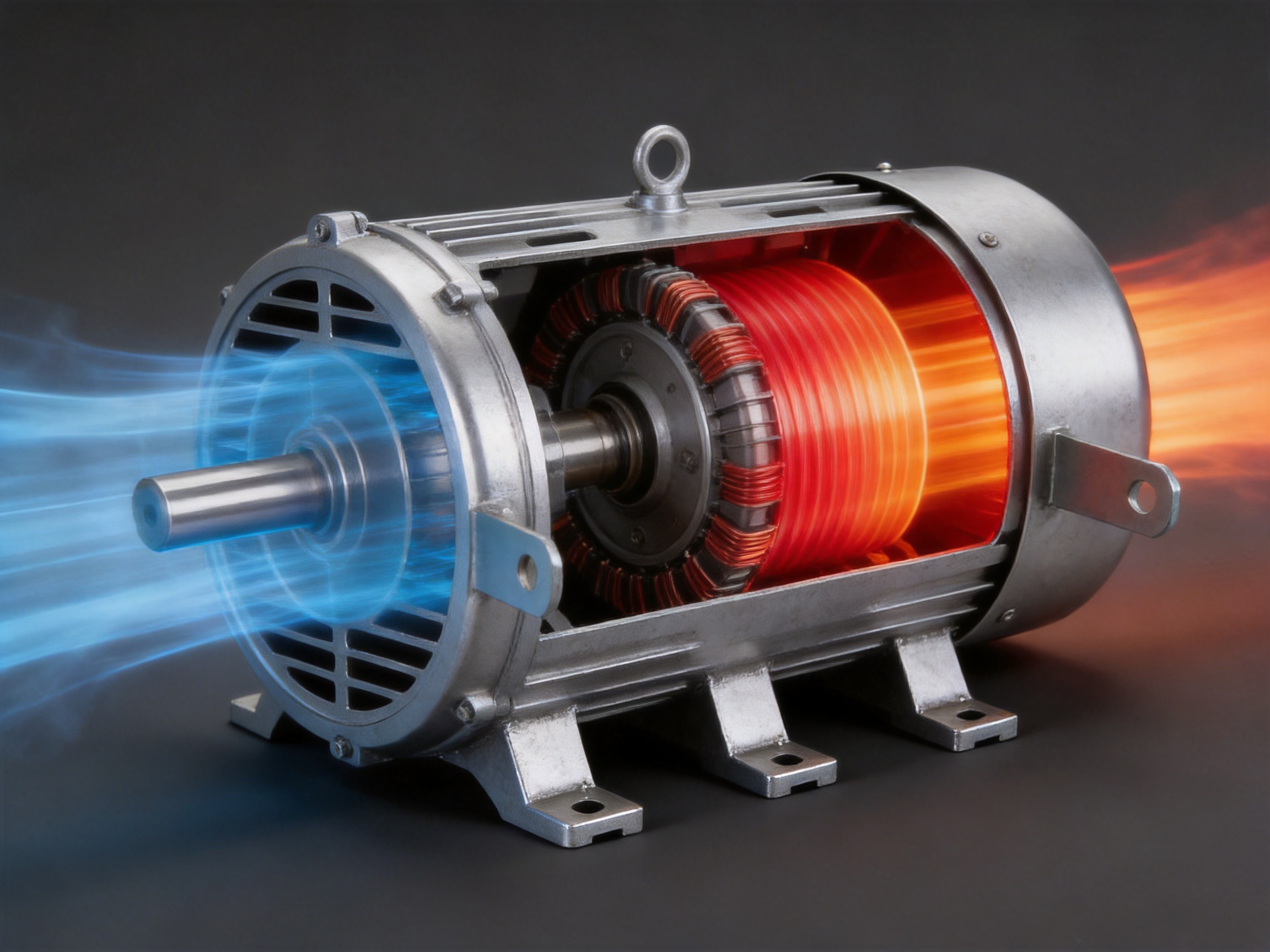
Heat is one of the most important factors affecting motor performance and operating life. Electrical losses in the stator windings, magnetic losses in the core, mechanical friction, and other energy losses generate heat during operation. If this heat remains inside the motor for too long, the temperature of the winding insulation and other components can rise. Sustained high temperature may accelerate insulation aging, reduce efficiency, and shorten the service life of the motor.
The housing incorporates ventilation holes at both ends. These openings establish an axial cooling path through the interior of the motor housing. Air can enter through one end, move along the internal motor space, and exit through the opposite end. This arrangement supports the removal of heat generated around the stator and rotor area, helping reduce temperature accumulation during continuous operation.
An axial ventilation channel is especially useful in compact motor assemblies because it does not require a large external cooling structure. The housing remains relatively simple while still providing a defined route for air movement. When combined with an appropriate fan, rotor airflow, or equipment ventilation system, the openings can support a continuous exchange of warmer internal air with cooler surrounding air.
The cooling performance of any ventilated motor housing depends on several factors, including the size and placement of the openings, the rotational speed of the motor, the surrounding equipment structure, ambient temperature, dust conditions, and the motor’s actual heat generation. The ventilation design of this housing provides a practical foundation for heat dissipation, while final motor thermal performance should be evaluated as part of the complete motor and equipment system.
Compared with a fully enclosed design that has limited natural airflow, the ventilated structure can provide a more direct path for heat removal. This may help the motor operate more consistently under suitable working conditions and can be especially valuable in industrial fans, exhaust equipment, and other applications where airflow is already a central part of the machine’s operation.
Inner Diameter 140 Steel Motor Housing With Three Brackets
Three-Point Mounting for Stability and Easier Leveling
The three welded mounting feet are one of the most distinctive features of this motor housing. The brackets are positioned to create a stable three-point support structure beneath the cylindrical body. Once the housing is secured, the three supports distribute the motor’s static load and help resist movement caused by vibration, starting torque, and normal operating forces.
Three-point support has a natural geometric advantage: three points define a plane. This means the housing can remain stable even when the mounting surface has minor irregularities. With a four-point arrangement, all four supports must be aligned accurately. If one support is slightly higher or lower, the assembly may rock, require shimming, or generate uneven stress after bolts are tightened.
The three-bracket configuration can therefore simplify equipment assembly. Installers may spend less time adjusting the mounting position, checking for rocking, or correcting small inconsistencies in the base. This is particularly helpful in field installation, replacement work, agricultural machinery, and compact production equipment where access to mounting fasteners may be limited.
The design also reduces the number of mounting points compared with four-foot alternatives. Fewer brackets can mean lower material consumption, fewer welded joints, reduced weight, and a simpler installation procedure. These benefits do not eliminate the need for proper bolt tightening and base preparation, but they can make the overall motor mounting process more straightforward.
The specified bracket bolt-hole center distance is 280 mm. This dimension gives equipment designers a clear reference for base layout and helps users confirm compatibility before ordering or installing the housing. Accurate mounting dimensions are especially important when the housing is being used as a replacement component in an existing machine.
Advantages Compared with Conventional Alternatives
A motor housing should not be evaluated only by its material or external appearance. Its practical value comes from how effectively it integrates structure, cooling, installation, manufacturing efficiency, and long-term usability. This product offers several design advantages over conventional housings that may rely on heavier construction, four-point support, or less coordinated ventilation.
Balanced Weight and Structural Performance
The 1.5 mm steel wall is designed to avoid excessive material use while retaining the basic stiffness needed for a motor enclosure. A heavy-wall housing may provide additional mass, but that extra weight can increase handling effort, shipping cost, equipment weight, and material consumption. For compact motor applications, a properly formed thinner wall can be a more efficient solution.
The cylindrical form contributes to structural efficiency. Curved sheet metal distributes external forces around the body more effectively than a flat sheet with the same thickness. When the housing is correctly formed and supported by welded brackets, the structure can deliver a dependable combination of strength and lightness.
Improved Installation Practicality
The three-point mounting structure can offer a practical advantage over four-point arrangements. It reduces the possibility of rocking caused by uneven bases and may make leveling faster. This can lower installation labor and reduce the need for additional shims or adjustment procedures.
The welded feet are integrated into the housing rather than supplied as separate loose components. This helps maintain a unified assembly and reduces the number of individual parts that must be handled during motor production. The mounting brackets can be positioned during controlled factory welding, helping achieve consistent geometry from one housing to the next.
Cooling-Oriented Configuration
Ventilation openings at both ends support axial airflow through the housing. This configuration is more purposeful than relying only on incidental heat transfer from the external shell. The openings create a defined passage that can work with the motor’s internal airflow and the surrounding machine’s ventilation arrangement.
Efficient heat removal can help support stable operation in applications where the motor runs for extended periods. It may also help designers avoid oversizing the housing solely to manage heat, although complete thermal validation remains necessary for each motor design.
Compact Application Fit
With a height of 114.3 mm and an inner diameter close to 140 mm, this housing is suited to equipment where the motor must fit within a restricted envelope. The compact design is relevant to industrial fans, exhaust units, packaging machines, food processing equipment, and agricultural machinery.
Smaller external dimensions can make it easier to place the motor near other components, route cables, maintain access to service areas, and design a compact finished product. The housing’s dimensions also give equipment manufacturers a defined reference when developing frames, brackets, guards, and covers.
Manufacturing Efficiency
The product is based on a formable steel body with welded brackets, a configuration well suited to repeatable industrial production. Compared with a more complex cast or heavily machined structure, a stamped and welded design can reduce material waste and shorten certain production steps. It can also provide flexibility for customers who require modifications to bracket shape, hole position, ventilation arrangement, or surface treatment.
Manufacturing efficiency is particularly important for customers purchasing motor housings in volume. Consistent processes can support stable pricing, predictable lead times, and repeatable quality. The ability to combine stamping, welding, machining, assembly, and finishing under one manufacturing organization also reduces the need to coordinate multiple external suppliers.
Material Selection: SPCC, ST12, and DC01
The housing can be manufactured using SPCC, ST12, or DC01 material specifications. These designations are widely associated with low-carbon cold-rolled steel used in sheet-metal forming and general fabrication. Their suitability for motor housing production comes from their balance of formability, surface quality, availability, and compatibility with welding and finishing processes.
Formability is important because the flat steel sheet must be shaped into a cylindrical body without excessive cracking, wrinkling, or distortion. Good forming behavior helps manufacturers achieve a consistent inner diameter and smooth external profile. It also supports efficient production of mounting feet and other formed features when the product design includes them.
Weldability is equally important. The three mounting brackets must be attached securely to the cylindrical body. A material specification compatible with controlled welding can help reduce defects and support consistent joint strength. Welding parameters still need to be selected according to material thickness, equipment capability, joint design, and production speed.
Material selection may be adapted to customer requirements, application conditions, and surface treatment plans. For equipment used in humid, corrosive, or washdown environments, the steel surface may require an appropriate coating, plating, painting, or other protective treatment. The standard material information should therefore be considered together with the intended environment and the customer’s corrosion-resistance expectations.
For demanding applications, customers should confirm the required steel grade, thickness tolerance, mechanical properties, surface condition, and finishing requirements before production. The manufacturer can then align material purchasing, forming parameters, welding procedures, and inspection standards with the customer’s technical specification.
Advanced Manufacturing Process
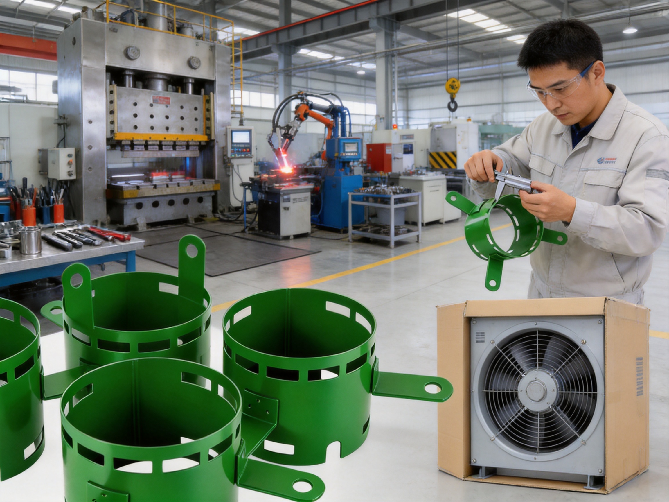
Jiangsu Yufeng Electric Co., Ltd. integrates stamping, welding assembly, machining, and surface treatment. This full-process capability is a significant advantage for motor housing customers because it allows the product to move through coordinated production stages under one manufacturing system.
Engineering and Product Development
Production begins with technical review and process planning. Engineers evaluate the customer’s drawings, dimensional requirements, material selection, bracket positions, ventilation openings, tolerance requirements, and intended application. This stage helps identify potential forming challenges and confirms that the design can be manufactured consistently.
For a housing with an inner diameter of 139.3 mm, height of 114.3 mm, and wall thickness of 1.5 mm, process planning must account for forming springback, weld distortion, dimensional change, and inspection access. The relationship between the cylindrical body and the three mounting brackets must also be considered because welding can influence roundness and alignment.
An experienced engineering team can improve manufacturability before mass production begins. With an average of more than 20 years of experience, the company’s engineering personnel are positioned to provide technical support from product development through production ramp-up. This experience can help customers convert a concept or drawing into a stable production process.
Steel Preparation and Stamping
Stamping and sheet-metal forming are used to produce the housing body and related components. Proper material preparation is essential. Steel coils or sheets must be checked for specification, thickness, surface condition, and consistency before entering production.
Tooling and forming parameters are selected according to the housing geometry. The objective is to create a cylindrical body with a stable diameter, controlled height, and acceptable surface condition. Accurate tooling can reduce variation and help ensure that the stator installation area remains within the required dimensional range.
Stamping production can provide high repeatability for volume orders. Once the tooling and process parameters have been validated, the same basic operation can be repeated efficiently. This supports consistent product output and helps reduce the unit cost of large production runs.
Welding Assembly
The mounting feet are welded to the lower section of the housing. Welding fixtures help position the brackets in relation to the cylindrical body and to one another. Controlled positioning is necessary to maintain the 280 mm bolt-hole center distance and to ensure that the finished housing sits correctly on the customer’s equipment base.
Automated welding equipment can improve repeatability by maintaining consistent travel speed, current, positioning, and weld placement. Automation may also reduce variation associated with manual handling. The use of suitable fixtures is important because the thin 1.5 mm wall must be supported during welding to minimize distortion.
Welding quality involves more than visual appearance. The joint must provide suitable mechanical strength, and the bracket must remain correctly aligned after cooling. Production inspection may include checks for weld continuity, bracket location, deformation, surface defects, and dimensional accuracy.
Machining and Dimensional Finishing
Machining facilities allow the manufacturer to complete precision features that may not be achievable through stamping and welding alone. Depending on the customer’s drawing, machining may be applied to mounting holes, end features, reference surfaces, or other areas requiring closer dimensional control.
Machining can also be used to correct or refine interfaces that must connect with other motor components. The exact process depends on the design and tolerance requirements. Integrating machining within the same manufacturing organization helps reduce transportation between suppliers and makes it easier to coordinate dimensional references across production stages.
Surface Treatment and Finishing
Surface treatment protects the steel from environmental exposure and contributes to the appearance and serviceability of the finished housing. The appropriate treatment depends on the application, ambient humidity, contact with chemicals, cleaning procedures, and customer expectations.
Finishing operations may include cleaning, preparation, coating, painting, or other specified treatments. A consistent surface-treatment process can improve coating adhesion and help ensure uniform appearance. For applications in food processing or other hygiene-sensitive environments, the selected finish should be reviewed against the equipment’s cleaning and regulatory requirements.
Inspection and Quality Control
Inspection instruments are used to evaluate the finished housing. Dimensional checks may cover inner diameter, outer diameter, height, wall thickness, bracket location, bolt-hole center distance, and overall roundness. Visual inspection can identify dents, burrs, incomplete welds, sharp edges, coating defects, and other surface issues.
Quality control should be applied throughout the process rather than only at the final stage. Incoming steel inspection, first-piece approval, in-process checks, welding verification, machining inspection, and final product review all contribute to a more reliable result. This approach can help identify process drift before a large quantity of nonconforming parts is produced.
Application Areas
Industrial Fans and Exhaust Equipment
Industrial fans and exhaust equipment often require motors that can operate continuously while moving air through a facility or process system. The housing’s axial ventilation openings complement applications where airflow is already central to the equipment. The compact cylindrical body can also fit within fan assemblies and protective frames.
The three mounting feet provide a stable connection to the equipment base. This can be helpful where vibration resistance and accurate positioning are important. Correct installation remains essential, including appropriate fasteners, base stiffness, shaft alignment, and balancing of the complete fan assembly.
Agricultural Machinery
Agricultural machinery may operate in dusty, humid, or variable-temperature environments. Motors used in ventilation systems, feeding equipment, conveyors, pumps, and processing units require housings that can provide structural support while remaining practical to replace and maintain.
The steel body and welded feet provide a durable mechanical platform for these applications. Depending on the environmental exposure, customers may select a suitable surface treatment or additional protective measures. Ventilation openings should be evaluated against the level of dust, moisture, and debris present in the working environment.
Food Processing Equipment
Food processing machinery often places emphasis on cleanliness, maintenance access, corrosion control, and reliable continuous operation. The housing can be incorporated into compact motors used in conveyors, mixers, packaging lines, exhaust systems, and auxiliary machinery.
For food-related applications, the complete motor assembly and surface treatment should be selected according to the cleaning method and operating environment. Customers should specify whether the equipment is exposed to water, detergents, steam, oils, or food particles. The housing design provides a starting point, while the final finish and sealing arrangement must be selected for the actual conditions.
Packaging Machinery
Packaging equipment often uses compact motors to drive rollers, belts, feeders, cutters, and other mechanisms. Space is frequently limited, and components must be mounted accurately to maintain repeatable machine performance. The 114.3 mm housing height and three-point support arrangement can be useful for equipment designers working within a restricted installation envelope.
The housing’s defined mounting dimensions allow the machine frame to be designed around a consistent bolt-hole layout. Its light construction may also help reduce the weight of moving or modular equipment sections.
Household and General Industrial Equipment
The housing may also be used in selected household appliances, general industrial drives, and special equipment where the dimensional envelope and thermal requirements are appropriate. The company’s broader production capabilities support different customer requirements, including variations in material, bracket arrangement, machining, and surface finish.
Design Considerations for Motor Integrators
Customers integrating this housing into a motor should review the internal fit between the stator and the housing. The specified inner diameter is 139.3 mm, but the final fit must be determined with consideration for stator dimensions, tolerances, assembly method, operating temperature, and the motor’s mechanical design.
Thermal performance should be evaluated using the complete motor assembly. Ventilation openings may improve airflow, but their effectiveness depends on the rotor, fan, end covers, internal clearances, external guards, and surrounding equipment. Testing under expected load and ambient conditions is recommended before finalizing a product for continuous operation.
Mounting design should account for the 280 mm bracket bolt-hole center distance, the orientation of the three feet, fastener size, base thickness, and required clearance for tools. The equipment base should be sufficiently rigid to prevent excessive vibration. Fasteners should be tightened according to the equipment designer’s requirements, and the motor should be aligned with connected shafts, belts, fans, or gear systems.
Customers should also identify whether the housing will be exposed to water, corrosive chemicals, salt, dust, high humidity, or frequent cleaning. These factors influence the selection of material protection and the design of ventilation covers or filters. A ventilated housing is advantageous for heat removal, but the ventilation system must be compatible with the environmental protection level required by the application.
Quality, Reliability, and Production Capacity
Jiangsu Yufeng Electric Co., Ltd. has approximately 40 years of experience in motor housing manufacturing. This experience supports the development of practical production methods for stamped, welded, machined, and finished components. Long-term specialization can help a manufacturer understand common housing defects, assembly challenges, dimensional risks, and customer expectations.
The company has served more than 50 customers and reports an annual production capacity of more than 5 million units. This production scale is relevant to customers seeking a stable supply of motor housings for ongoing programs. Capacity alone does not guarantee quality, but it indicates that the manufacturer has established production resources and experience with repeat orders.
Its manufacturing organization includes stamping lines, automated welding equipment, machining facilities, and inspection instruments. The combination of these resources supports a coordinated production flow from steel processing to finished delivery. It also gives the company greater control over process changes and technical communication.
For customers developing a new motor, cooperation with a full-process manufacturer can simplify the transition from prototype to mass production. Engineering changes can be reviewed with the teams responsible for tooling, forming, welding, machining, and finishing. This reduces the risk that a design suitable in theory will encounter unexpected production limitations later.
Fast response is another important supplier characteristic. Motor housing projects may require drawing review, sample production, dimensional reports, trial assembly, corrective action, and production scheduling. A manufacturer with internal engineering and production resources can often coordinate these activities more efficiently than a fragmented supply chain.
Customization and OEM Support
Although the product is specified with a 139.3 mm inner diameter, 114.3 mm height, 1.5 mm wall thickness, and three welded brackets, motor housing applications frequently require customization. Potential adjustments may include material grade, wall thickness, housing height, internal diameter, ventilation-hole pattern, bracket geometry, bolt-hole spacing, weld specifications, and surface treatment.
Customization should be evaluated as a complete system. Changing the wall thickness may affect forming, weight, rigidity, welding heat input, and dimensional stability. Moving a bracket may alter load distribution and vibration behavior. Enlarging ventilation openings may influence cooling performance but could also affect protection against dust or accidental contact. Each change should therefore be reviewed by engineering and validated through samples or testing where appropriate.
OEM support is particularly valuable when the motor housing forms part of a proprietary equipment platform. The supplier can work from customer drawings, three-dimensional models, prototypes, or performance requirements. It can also support the preparation of production drawings and inspection criteria to help ensure that the finished component matches the customer’s assembly process.
Prototype and trial production are useful for checking stator fit, bracket alignment, mounting stability, cooling behavior, and compatibility with the final motor. After approval, process documentation and inspection standards can be established for mass production. This staged approach helps reduce risk before high-volume manufacturing begins.
Recommended Inspection Points
For incoming inspection, customers may verify the material specification, surface condition, major dimensions, and general workmanship. The inner diameter should be checked at multiple positions to evaluate roundness and local deformation. The housing height and outer diameter should be measured using suitable calibrated equipment.
The 1.5 mm wall thickness should be confirmed according to the agreed tolerance. The measurement method should avoid distortion of the sheet and should be applied consistently. If the housing includes formed or welded features, thickness may vary slightly in localized areas, so the inspection plan should identify the critical zones.
The three mounting feet should be checked for position, orientation, weld quality, and contact stability. The 280 mm bolt-hole center distance should be measured using a controlled reference method. The housing should also be placed on a reference surface to check whether it rocks or whether one foot sits outside the intended support plane.
Ventilation openings should be inspected for correct location, adequate clearance, burr removal, and unobstructed airflow. Sharp edges should be eliminated where they could interfere with assembly, maintenance, wiring, or operator safety. Surface treatment should be inspected for uniformity, adhesion, coverage, and damage caused during handling.
Where required by the customer, additional inspection can include weld testing, coating-thickness measurement, dimensional reports, first-article inspection, and trial assembly with representative stator or motor components. The inspection level should be matched to the application’s risk, production volume, and quality requirements.
Installation and Operating Recommendations
Before installation, confirm that the motor, stator, end covers, shaft, and housing are compatible. Check the inner diameter, axial height, bracket-hole spacing, and ventilation arrangement against the motor drawing. The mounting base should be clean, rigid, and free from burrs or debris that could prevent the three brackets from sitting correctly.
Install the housing using fasteners that match the bracket-hole size and the equipment designer’s structural requirements. Tighten fasteners evenly to avoid unnecessary distortion. Because the housing uses three-point support, confirm that all three feet make stable contact with the mounting surface before final tightening.
Allow sufficient clearance around the ventilation openings. Do not block the air path with cable bundles, guards, insulation, or adjacent structures unless the cooling system has been designed and tested for that arrangement. If the application operates in a dusty or wet environment, consider suitable protective screens, filters, or sealing measures that do not cause excessive airflow restriction.
During initial operation, monitor vibration, temperature, noise, and mounting stability. Unusual vibration may be related to rotor imbalance, shaft misalignment, loose fasteners, fan imbalance, or an unsuitable base rather than the housing alone. Temperature should be evaluated under representative load and ambient conditions.
Regular maintenance should include checking mounting fasteners, inspecting the ventilation openings, removing accumulated dust or debris, and examining the surface finish for damage or corrosion. Maintenance intervals should be based on the operating environment and the equipment manufacturer’s instructions.
Why Full In-House Production Matters
A motor housing passes through several manufacturing stages, and quality problems can arise when responsibility is divided among too many suppliers. A stamping supplier may not control welding. A welding supplier may not control machining. A finishing supplier may not have visibility into the original material or dimensional condition. Each transfer can introduce delays, communication gaps, or inconsistencies.
Full in-house production gives Jiangsu Yufeng Electric greater control over the complete process. The same organization can coordinate material preparation, stamping, welding, machining, surface treatment, inspection, and delivery. This arrangement supports clearer accountability and can make corrective action faster when a dimensional or functional issue is identified.
Integrated production also supports better process optimization. For example, engineers can adjust a stamping operation based on welding results, modify a bracket fixture to improve final alignment, or revise a surface-treatment step according to customer feedback. Such coordination is valuable when the housing has tight interfaces or is produced in large volumes.
In-house capabilities can also reduce logistics between production stages. Fewer external transfers may lower handling damage, simplify scheduling, and improve traceability. For OEM customers, this may provide a more predictable path from approved drawing to repeat production.
Commercial Value for Equipment Manufacturers
The commercial value of a motor housing includes more than its purchase price. Lightweight construction can reduce handling and shipping costs. Efficient stamping and welding can support competitive unit pricing. Integrated machining and finishing can reduce supplier-management effort. Stable dimensions can reduce assembly labor and rework.
The three-bracket design may also provide downstream savings. If the housing is easier to level and install, equipment manufacturers may reduce assembly time. If the mounting arrangement reduces the need for shims or repeated adjustments, production consistency can improve. These benefits are especially relevant in high-volume equipment manufacturing.
Reliable cooling can support the design of a compact motor system. When heat is managed effectively, equipment designers may have greater flexibility in packaging the motor within a limited space. The final thermal result must still be validated, but the housing provides a ventilation-oriented structure that supports this goal.
Long-term supply capability is another commercial consideration. With reported experience, customer service, production capacity, and multiple in-house processes, the manufacturer is positioned to support both development projects and continuing orders. Customers can discuss specifications, samples, production schedules, and quality requirements with one specialized supplier.
Frequently Asked Questions
What is the inner diameter of the housing?
The specified inner diameter is 139.3 mm. This dimension should be reviewed together with the stator’s actual dimensions, assembly tolerances, and the motor manufacturer’s fit requirements.
What is the external diameter?
The listed outer diameter is 142.3 mm. The difference between the listed inner and outer diameters corresponds to the nominal 1.5 mm wall thickness on each side.
What is the height of the housing?
The housing height is 114.3 mm. This compact axial dimension is suitable for motor assemblies installed in restricted spaces, subject to confirmation of the complete motor’s dimensions.
What material is used?
The available material specifications are SPCC, ST12, and DC01. The final material should be confirmed according to the customer’s drawing, mechanical requirements, forming needs, welding process, and surface-treatment expectations.
How many mounting brackets does the housing have?
The housing has three welded mounting brackets. They form a three-point support structure intended to provide stable installation and easier leveling than many four-point arrangements.
What is the bracket bolt-hole center distance?
The specified bracket bolt-hole center distance is 280 mm. Customers should verify the measurement direction and reference points against the approved drawing before designing the equipment base.
Why use three mounting points instead of four?
Three points define a stable plane and are generally easier to level on a surface with minor irregularities. The arrangement can also reduce material usage, weight, and the number of mounting adjustments required during assembly.
How does the housing support heat dissipation?
Ventilation openings at both ends create an axial airflow path through the housing. This allows air to pass through the motor interior and helps remove heat generated by the stator and rotor. Complete thermal performance depends on the motor design and operating conditions.
Is the housing suitable for continuous operation?
The design is intended to support motors used in continuous-duty applications where appropriate. However, continuous-operation suitability must be confirmed through complete motor thermal testing, including load, ambient temperature, airflow, and installation conditions.
Can the housing be customized?
Customization may be possible for dimensions, material, ventilation openings, bracket configuration, bolt-hole spacing, machining, welding, and surface treatment. Each change should be reviewed by engineering to ensure that manufacturability and performance are maintained.
Which industries can use this motor housing?
Potential applications include industrial fans, exhaust equipment, agricultural machinery, food processing equipment, packaging machinery, household appliances, general industrial drives, and other medium-to-small power equipment.
What manufacturing capabilities does the supplier provide?
The supplier integrates stamping, automated welding, machining, assembly, surface treatment, and inspection. This supports full-process manufacturing from steel processing to finished motor housing delivery.
What should customers provide when requesting a quotation?
Customers should provide drawings or three-dimensional models, required material, annual quantity, target application, mounting dimensions, ventilation requirements, surface-treatment expectations, inspection standards, packaging requirements, and delivery schedule. Sample parts or a representative motor assembly can also help confirm fit and function.
Conclusion
The Inner Diameter 140 Steel Motor Housing with Three Brackets is a compact, ventilation-oriented steel housing designed for practical motor integration. Its 139.3 mm inner diameter, 114.3 mm height, and 1.5 mm wall thickness provide a balanced configuration for medium-to-small power equipment. The cylindrical body supports a compact installation envelope, while the end ventilation openings establish an axial airflow path for heat dissipation.
The three welded mounting feet are a major functional advantage. They provide stable support, help resist vibration, simplify leveling, and reduce the complexity associated with four-point mounting. The 280 mm bolt-hole center distance gives equipment designers a clear installation reference, and the lightweight structure can reduce material use and handling requirements.
Beyond the product design, the manufacturing system is an important source of value. Jiangsu Yufeng Electric Co., Ltd. combines engineering development, stamping, automated welding, machining, surface treatment, assembly, and inspection. Its reported manufacturing experience, production capacity, customer base, and technical team support the needs of customers seeking both prototype assistance and reliable mass production.
For equipment manufacturers, motor producers, and industrial buyers, this housing offers a practical combination of dimensional control, cooling support, mounting stability, production efficiency, and customization potential. Proper application review remains essential, but the product provides a strong foundation for reliable motor assemblies used in compact and heat-sensitive equipment.
References
1. Product specification data for ID140008 Inner Diameter 140 Steel Motor Housing with Three Brackets.
2. General engineering principles for electric motor housing design, thermal management, and structural support.
3. Technical guidance on cold-rolled low-carbon steel forming, welding, machining, and surface treatment.
4. Standard manufacturing practices for stamped sheet-metal components and welded motor assemblies.
5. Application engineering considerations for industrial fans, exhaust systems, agricultural machinery, food processing equipment, and packaging machinery.
6. Supplier-provided information concerning integrated stamping, welding, machining, assembly, inspection, and annual production capacity.

 Previous