

 English
 Español
Content
- 1 Product Overview
- 2 Why Steel Is a Practical Motor Housing Material
- 3 Precision Dimensions for Controlled Motor Assembly
- 4 Welded Base for Stable Mechanical Mounting
- 5 Integrated T-Base Terminal Block
- 6 Advantages Compared with Conventional Housing Solutions
- 7 Manufacturing Process and Quality Approach
- 8 Engineering Support from Development to Mass Production
- 9 Applications and Selection Considerations
- 10 Installation and Assembly Guidance
- 11 Quality, Reliability, and Long-Term Value
- 12 Customization and Project Cooperation
- 13 Comparison of Key Product Characteristics
- 14 Why Choose an Integrated Manufacturing Partner
- 15 Recommended Customer Verification Checklist
- 16 Q&A
- 16.1 What is the inner diameter of this steel motor housing?
- 16.2 What is the housing height?
- 16.3 What materials are specified for the housing?
- 16.4 What is the base center distance?
- 16.5 How is the base attached to the housing?
- 16.6 What is the function of the T-base terminal block?
- 16.7 Can the housing withstand motor vibration?
- 16.8 Is the product suitable for customized motor projects?
- 16.9 Can the housing be used in industrial equipment?
- 16.10 Does the housing include surface treatment?
- 16.11 How should the terminal area be evaluated?
- 16.12 What manufacturing capabilities does the supplier provide?
- 16.13 What industries does the company serve?
- 16.14 What information should be provided for a quotation?
- 17 Conclusion
- 18 References
- 19 Product: Inner Diameter 135 Steel Motor Housing With Base and T-Base
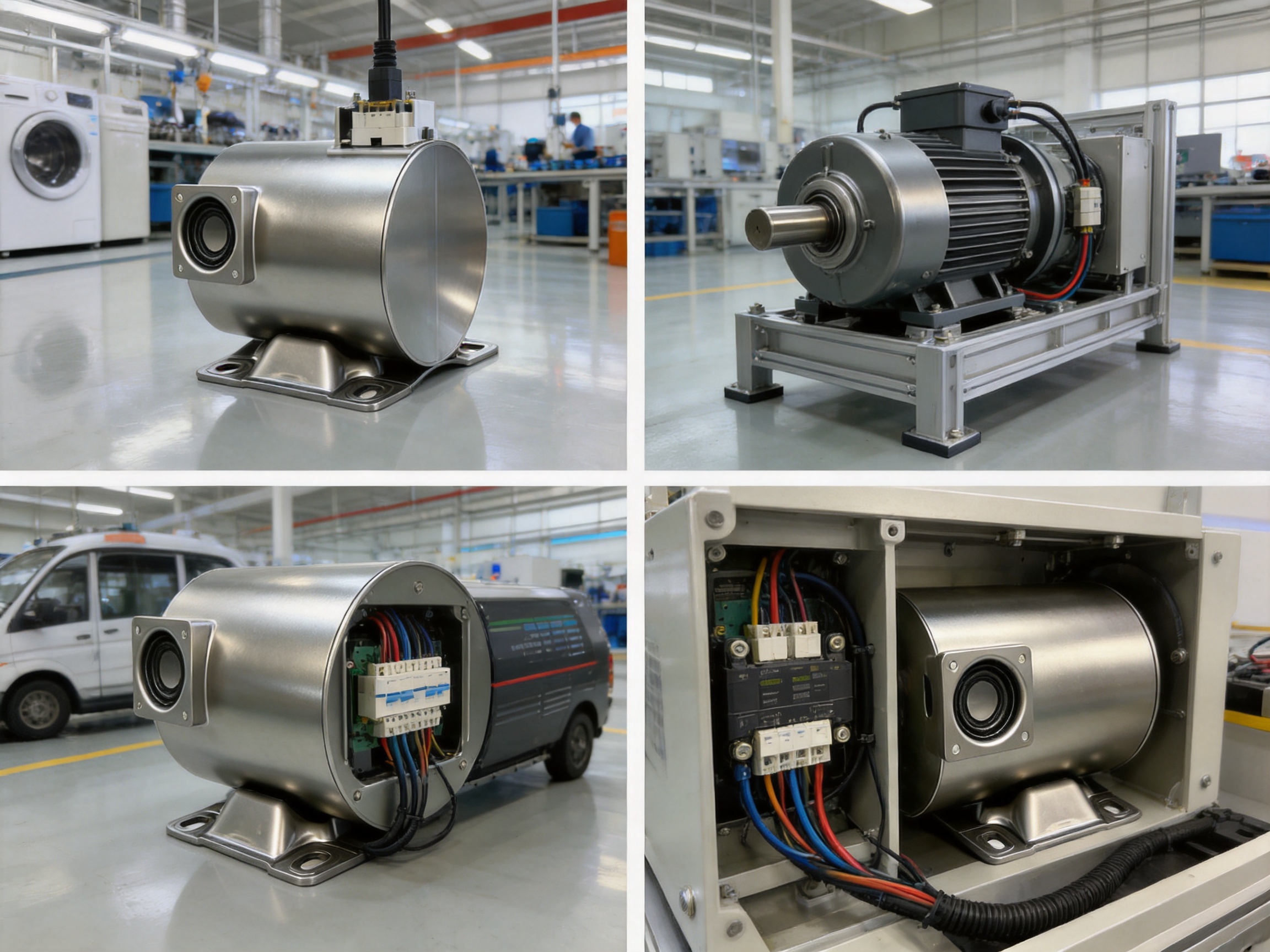
Motor housings are essential structural components in electric motors. They protect internal parts, maintain the alignment of the rotor and stator, support mounting, assist with heat management, and contribute to the overall durability and safety of the finished motor. Although a housing may appear to be a relatively simple fabricated part, its dimensional accuracy, material consistency, welding quality, and mounting design directly influence motor performance and service life.
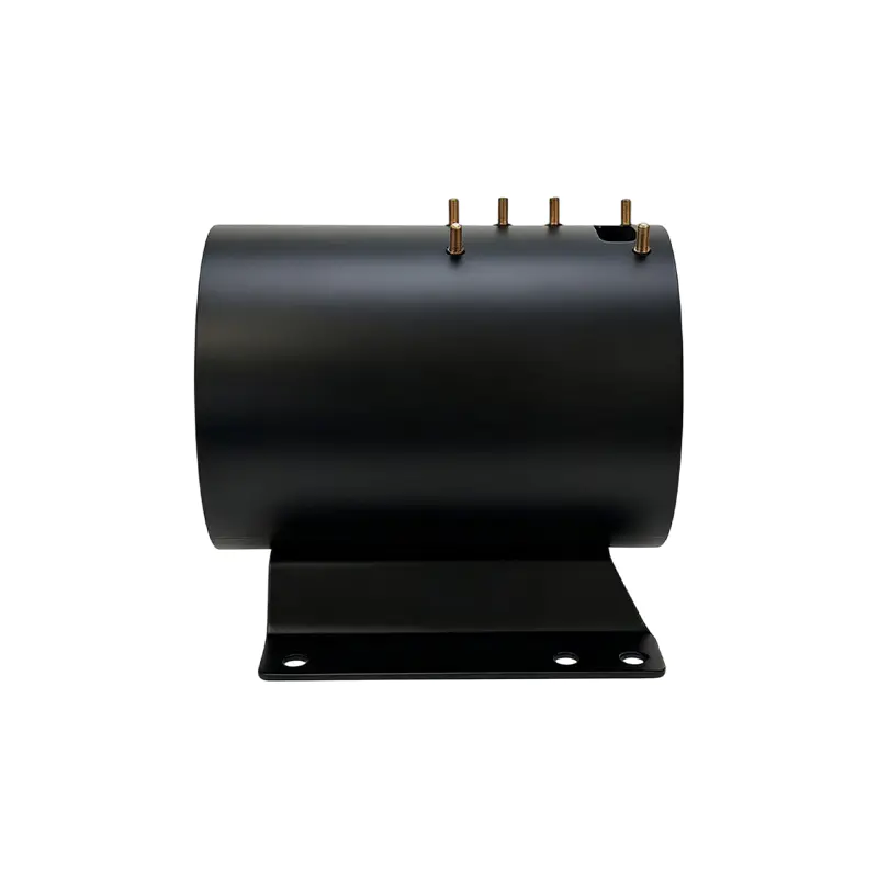
The Inner Diameter 135 Steel Motor Housing with Base and T-Base is designed for applications that require a compact, durable, and dependable motor enclosure. With an inner diameter of 135 millimeters, a height of 155 millimeters, a base center distance of 80 millimeters, and a material specification of SPCC, ST12, or DC01 steel, the housing provides a practical balance between structural strength, dimensional control, manufacturing efficiency, and installation convenience.
This product combines a precision-formed steel shell, a welded mounting base, and an integrated T-base terminal block. The result is a complete housing solution that supports both the mechanical and electrical requirements of a motor assembly. Instead of treating the housing, mounting structure, and terminal support as separate components, the design brings them together in one coordinated unit.
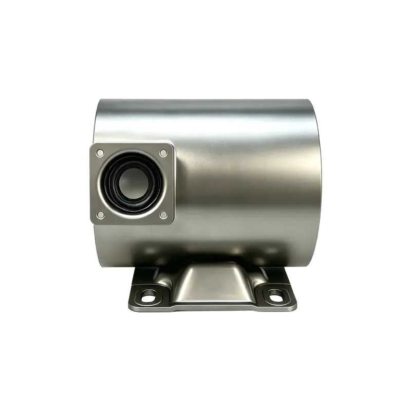
Inner Diameter 135 Steel Motor Housing With Base and T-Base
Product Overview
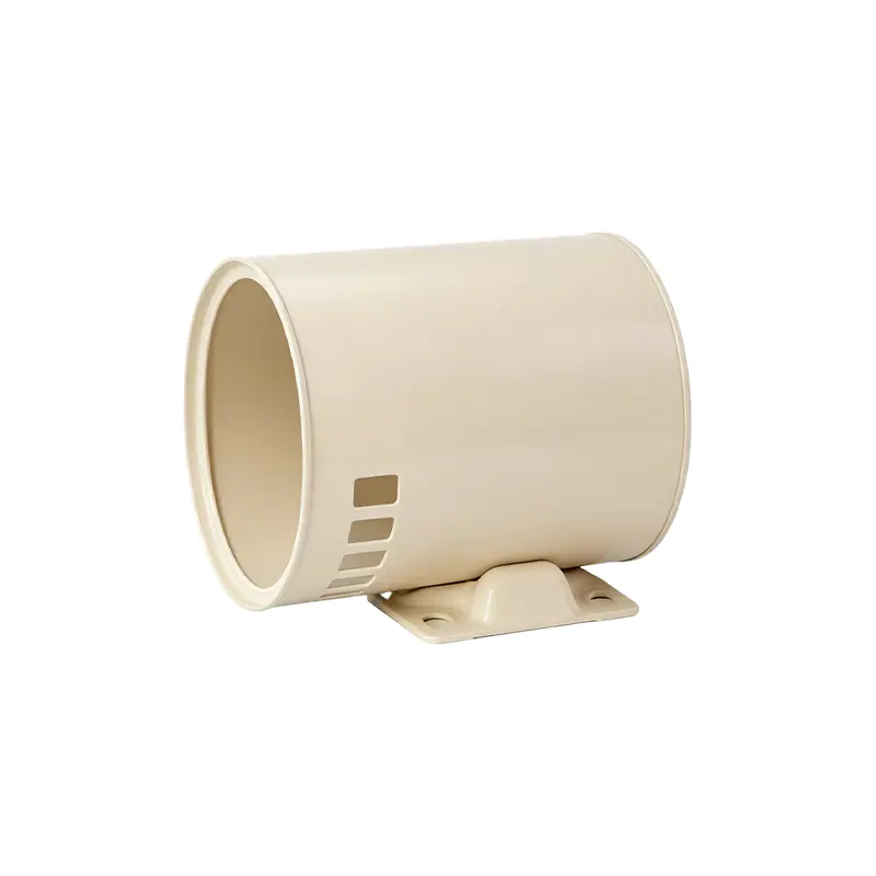
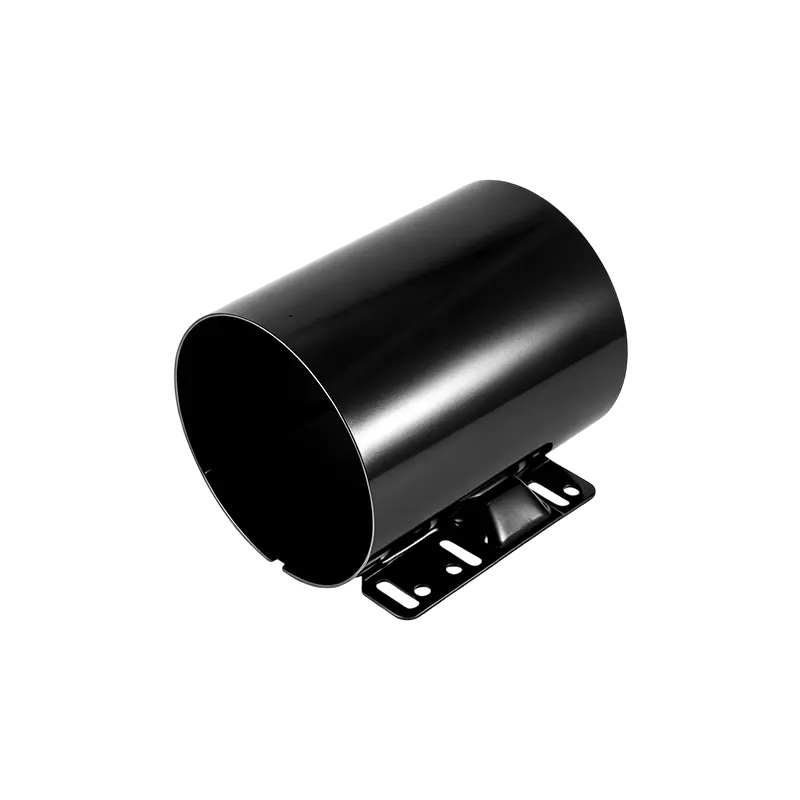
The Inner Diameter 135 Steel Motor Housing with Base and T-Base is manufactured for motor assemblies that require a nominal internal diameter of 135 millimeters and an overall housing height of 155 millimeters. The steel body creates a rigid enclosure around the motor’s active components, while the welded base provides a stable connection to the equipment frame or mounting platform.
The integrated T-base terminal block is welded onto the base. This feature provides a defined support point for motor power-wire connections and helps standardize the arrangement of the electrical connection area. By securing the terminal structure directly to the housing base, the design reduces the need for additional loose brackets and helps limit movement of the wiring connection during equipment operation.
The housing is identified as product ID135006 and belongs to the steel motor housing product category. It is suitable for customers seeking a fabricated steel motor enclosure rather than a purely cast or non-metallic housing solution. The structure can be incorporated into motor assemblies used in household appliances, industrial drives, new energy vehicle-related equipment, and special machinery, subject to the application’s detailed technical requirements.
The principal specifications are summarized below.
| Specification | Value |
|---|---|
| Product type | Steel motor housing with base and T-base |
| Product ID | ID135006 |
| Inner diameter | 135 mm |
| Height | 155 mm |
| Material specification | SPCC / ST12 / DC01 |
| Base center distance | 80 mm |
| Base construction | Gas-shielded welded steel structure |
| Terminal feature | Welded T-base terminal block |
These dimensions provide an identifiable starting point for design review, sample approval, tooling development, and production planning. Customers can use the stated inner diameter and height to compare the housing with the required motor stack, end-shield arrangement, insulation system, and available installation envelope.
Why Steel Is a Practical Motor Housing Material
Steel remains a widely used material for motor housings because it offers a strong combination of mechanical performance, process flexibility, availability, and cost control. SPCC, ST12, and DC01 are commonly associated with cold-rolled low-carbon steel grades used in fabricated and stamped components. Their suitability for a specific project depends on the customer’s drawing, thickness requirement, forming geometry, surface-treatment specification, and performance expectations.
A steel housing can provide effective resistance to deformation when the motor is exposed to vibration, handling, fastening loads, and operating forces. The material also supports a wide range of manufacturing methods, including cutting, stamping, forming, welding, machining, and surface finishing. This flexibility allows the housing design to include mounting features, brackets, terminal supports, and other functional details without relying on a single manufacturing process.
Compared with some non-metallic alternatives, steel can offer a more rigid mounting platform and a stronger foundation for welded attachments. Compared with certain cast structures, a fabricated steel housing can be advantageous when customers require a relatively lightweight design, faster design modifications, or economical production of customized geometries. The most suitable choice still depends on the operating environment, temperature, corrosion exposure, acoustic requirements, and target production volume.
For a motor housing with an integrated base and terminal support, steel also provides a coherent material platform. The main body, welded base, and terminal support can be designed as a coordinated assembly. This helps simplify the transfer of mechanical loads and supports consistent production control across the complete housing unit.
Precision Dimensions for Controlled Motor Assembly
The 135-millimeter inner diameter is the defining dimensional feature of this housing. Internal diameter control is important because the housing must accommodate the motor’s internal components while maintaining the intended relationship between the stator, rotor, end shields, bearings, and other parts. A housing that is too small may interfere with assembly, insulation, or clearance requirements. A housing that is too large may reduce positional stability or create unwanted gaps in the motor structure.
The 155-millimeter height also contributes to the fit of the complete motor assembly. It defines the available axial envelope and must be considered together with the length of the stator core, end-cover design, bearing arrangement, internal insulation, and any sealing or spacing components. Accurate control of height supports repeatable assembly and helps customers plan the overall motor package.
The 80-millimeter base center distance provides a defined mounting reference. A consistent center distance helps the housing interface with the customer’s equipment frame, mounting plate, bracket, or drive system. It also supports standardized fixture design and reduces the risk of installation variation during assembly.
Dimensional quality is not limited to the nominal figures listed in a product specification. A professional motor housing program also considers roundness, concentricity, flatness, perpendicularity, weld distortion, hole position, base alignment, and the relationship between the housing axis and the mounting surface. These characteristics should be confirmed through customer drawings, agreed tolerances, inspection plans, and sample validation.
Jiangsu Yufeng Electric Co., Ltd. integrates stamping, welding assembly, machining, surface treatment, and inspection capabilities. This integrated structure enables the manufacturer to coordinate critical dimensions across multiple operations rather than treating each process as an isolated subcontracting step. Better process coordination can improve production consistency and make it easier to identify the source of dimensional variation.
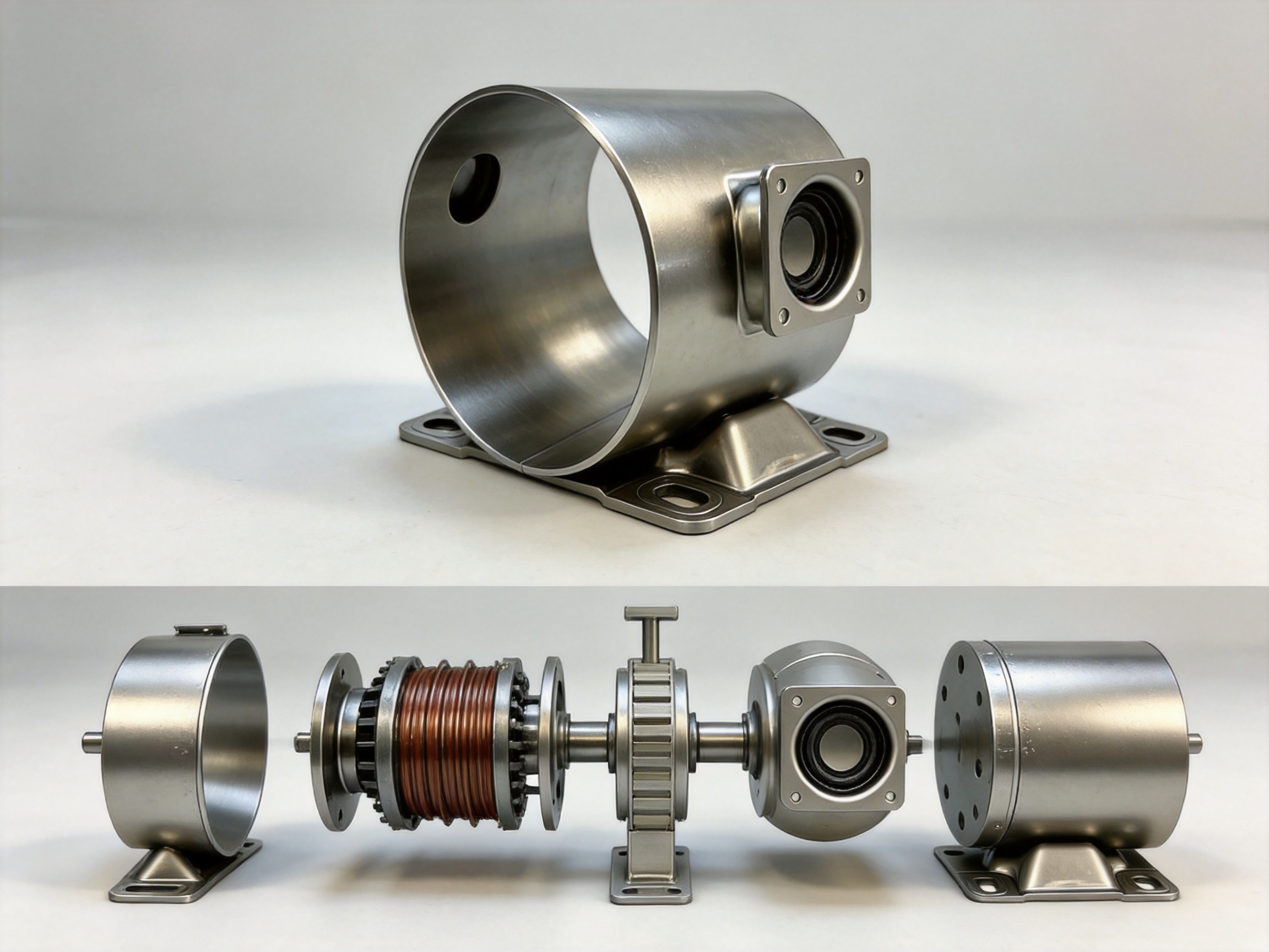
Welded Base for Stable Mechanical Mounting
The base is one of the most important functional features of this product. A motor housing does not merely surround the motor; it must also connect the motor to the equipment that drives, supports, or operates it. The welded base creates a firm mounting interface and helps transfer the motor’s weight, vibration, and operating loads to the external structure.
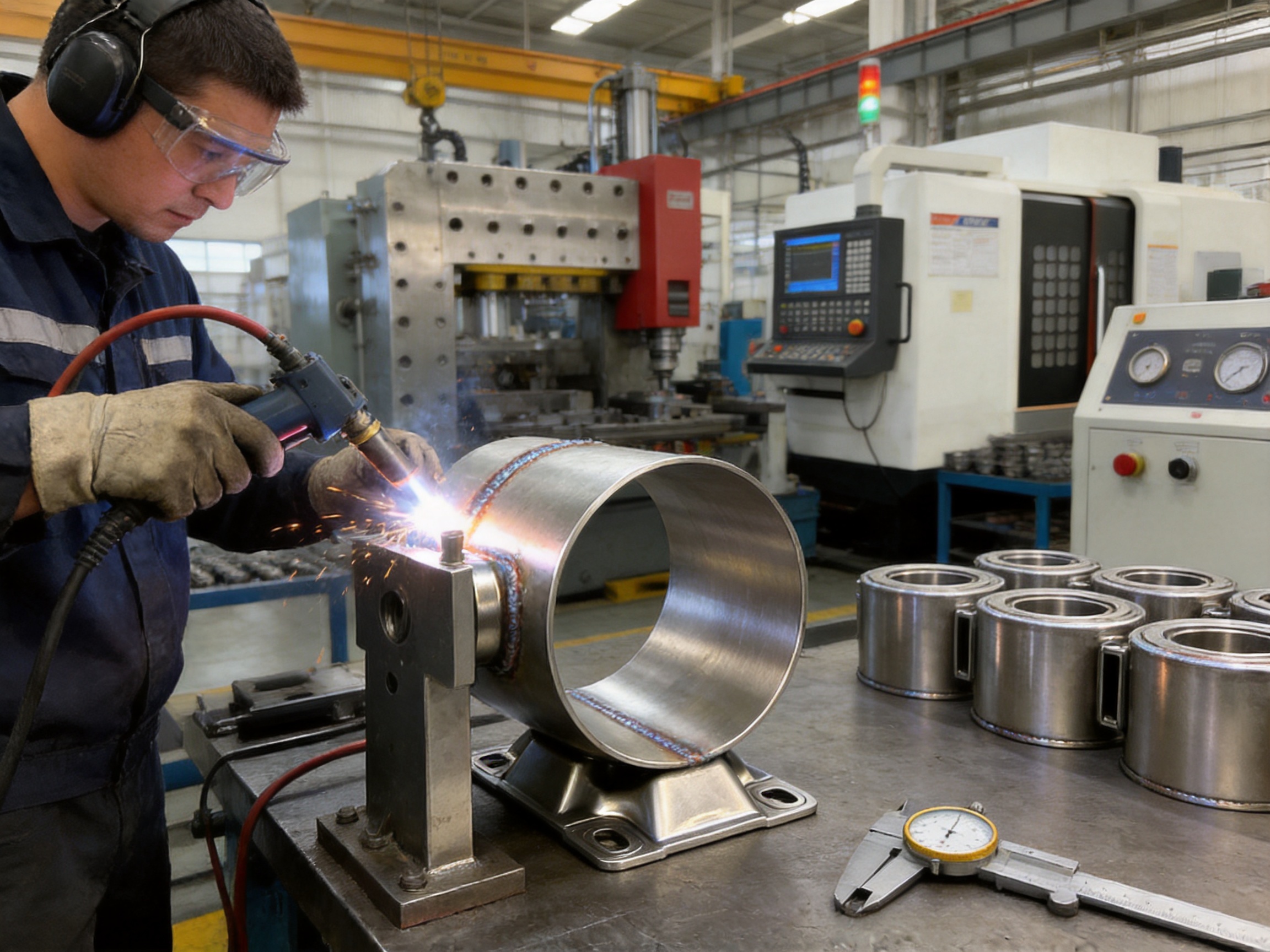
The base is produced using gas-shielded welding technology. In gas-shielded welding, a protective gas atmosphere helps reduce the effect of atmospheric contamination on the weld area. When the process is correctly selected and controlled, it can support a stable arc, consistent weld formation, and a cleaner finished joint. The specific welding parameters depend on the material grade, thickness, joint design, component geometry, and production equipment.
The product description highlights uniform and dense weld seams, a small heat-affected zone, and minimal spatter. These characteristics are valuable in motor housing production. Uniform seams help distribute loads along the joint. A dense weld structure supports the integrity of the connection. A relatively small heat-affected zone can help limit unnecessary thermal distortion in surrounding areas. Reduced spatter can improve appearance, reduce cleaning requirements, and lower the risk of unwanted particles remaining near the motor assembly.
A reliable welded base is particularly important when the motor operates continuously. Motors can generate repeated vibration, starting and stopping loads, torque reaction, and mechanical shocks. If the base is poorly attached, these forces may lead to loosening, cracking, deformation, or progressive fatigue damage. A controlled welding process helps create a more dependable connection between the housing body and the mounting structure.
Welding quality also influences assembly efficiency. Excessive spatter, inconsistent bead geometry, or distortion may interfere with subsequent machining, coating, mounting, or inspection. By controlling the welding operation and using suitable fixtures, the manufacturer can improve the repeatability of the base position and reduce corrective work.
Mechanical Benefits of the Base Design
The base supports several practical functions within the motor assembly. First, it provides a fixed location for attaching the motor to external equipment. Second, it helps maintain the orientation of the housing during operation. Third, it creates a platform for the T-base terminal block. Fourth, it contributes to the overall stiffness of the motor package.
The welded construction can be adapted to customer-specific requirements more readily than a highly integrated casting in some development situations. Base geometry, hole patterns, reinforcement features, and terminal support locations can be adjusted as part of an engineering review, provided that the revised design remains compatible with the manufacturing process and performance requirements.
Customers should evaluate the base together with the equipment mounting system. Important considerations may include bolt size, hole diameter, fastening method, mounting-surface flatness, load direction, vibration class, installation clearance, and access for maintenance. The listed 80-millimeter base center distance establishes a key reference, while the final interface should be confirmed against the customer’s assembly drawing.
Integrated T-Base Terminal Block
The T-base terminal block is a distinctive feature of this motor housing. Electrical connections are a critical part of motor reliability, and the terminal area must remain mechanically secure throughout the service life of the product. A terminal block that is inadequately supported may be affected by vibration, wire tension, repeated maintenance, or improper handling during installation.
In this design, the T-base terminal block is welded onto the housing base. The welded attachment creates a fixed support structure for the motor power wires. It also helps maintain a consistent position for the terminals, which can support standardized wiring procedures and more predictable assembly operations.
A stable terminal position can help reduce the possibility of loose connections. Loose wiring may increase contact resistance, create localized heating, interrupt current flow, or produce intermittent electrical faults. A firmly supported terminal area does not replace correct electrical design or proper fastening, but it provides a stronger mechanical foundation for the connection system.
The T-base may also contribute to the organization of the motor’s wiring path. When the terminal support is integrated into the housing design, wires can be routed with a more consistent relationship to the motor body. This may help reduce accidental contact with moving parts, sharp edges, or high-temperature areas, subject to the final wiring design and insulation system.
Electrical conductivity is influenced by the terminal materials, contact surfaces, fastening method, conductor preparation, and assembly torque. The welded steel support primarily provides mechanical fixation and positioning. Customers should separately confirm terminal material, insulation requirements, creepage and clearance distances, current rating, voltage rating, grounding arrangements, and any applicable electrical standards.
Mechanical and Electrical Functions in One Assembly
One advantage of combining the base and T-base terminal block in a coordinated housing design is the reduction of disconnected interfaces. A separate terminal bracket may require additional fasteners, positioning steps, or tolerance adjustments. An integrated welded support can simplify the assembly concept and create a repeatable relationship between the motor body, mounting base, and electrical connection area.
This integrated approach may also help reduce part count. Fewer separate brackets and fasteners can support more efficient assembly and reduce opportunities for missing components. It can also simplify purchasing and inventory management when the housing is delivered as a ready-to-assemble structural component.
However, the terminal assembly must still be verified for the intended application. Electrical safety depends on more than the presence of a welded terminal support. The complete motor design should address insulation, grounding, protection against accidental contact, environmental sealing, wire strain relief, creepage, clearance, and appropriate testing.
Advantages Compared with Conventional Housing Solutions
The Inner Diameter 135 Steel Motor Housing with Base and T-Base offers several potential advantages compared with more basic housing designs. These advantages relate to integration, structural support, manufacturing flexibility, and production consistency.
Integrated Mounting and Terminal Support
A conventional motor housing may require a separate mounting bracket and an independently installed terminal support. Each additional component introduces another interface, another tolerance relationship, and another assembly step. The product described here combines the housing body with a welded base and T-base terminal block, creating a more complete structural assembly.
This integration can reduce the number of loose components and support a cleaner assembly workflow. It may also reduce the time needed to position terminal hardware and mounting brackets during motor production. For customers purchasing housings for repeat assembly, an integrated configuration can improve standardization.
Strength Under Vibration and Impact
The welded base is intended to withstand continuous vibration and impact loads associated with heavy-duty motor operating conditions. A properly designed and manufactured welded joint can offer strong load transfer between the housing and base. This is particularly useful for applications in which the motor is mounted directly to a machine frame and exposed to repeated mechanical forces.
The housing’s steel construction also provides a rigid support structure. The combination of a steel shell and welded base can be preferable to a lightweight structure that lacks adequate resistance to deformation. The final performance depends on material thickness, weld design, mounting conditions, load spectrum, and validation testing, but the basic configuration is well suited to robust motor assembly requirements.
Controlled Manufacturing Flexibility
Fabricated steel construction supports design customization. Manufacturers can adjust formed shapes, base geometry, terminal support arrangements, surface treatments, and selected machining details to meet project requirements. This flexibility is useful for original equipment manufacturers that need a housing matched to a particular motor platform or equipment interface.
Jiangsu Yufeng Electric’s combination of stamping, welding, machining, assembly, and finishing capabilities supports this type of coordinated development. A customer can discuss the housing requirement with a manufacturer that understands both the individual processes and the complete product route.
Efficient Use of Material and Process Capability
Steel motor housings can be produced through controlled forming and welding processes that use material efficiently. Compared with a heavily overdesigned structure, a properly engineered fabricated housing can maintain necessary stiffness without adding unnecessary mass. The stated product is described as compact and lightweight while retaining sufficient strength for its intended role.
Weight reduction can help with motor handling, installation, shipping, and equipment integration. It may also support a smaller overall machine package. Any weight advantage must be assessed together with vibration, heat, acoustic, and durability requirements, but a compact steel housing can be a practical compromise between portability and structural reliability.
Consistent Terminal Positioning
The welded T-base provides a repeatable reference for power-wire connections. A consistent terminal position helps assembly operators follow standardized procedures and can support the use of repeatable jigs or wiring fixtures. This is especially valuable in medium- and high-volume production, where small variations can accumulate into significant efficiency and quality differences.
Manufacturing Process and Quality Approach
The production of a reliable motor housing requires more than forming a steel shell. The process must control material quality, geometry, welding, machining, surface condition, assembly, and inspection. Jiangsu Yufeng Electric has developed an in-house manufacturing structure covering stamping, welding assembly, machining, surface treatment, and inspection.
Material Preparation
Production begins with the selection and preparation of suitable steel material. The listed material specifications are SPCC, ST12, and DC01. These materials are commonly used for cold-rolled steel components, but the final grade, thickness, temper, surface condition, and certification requirements should be confirmed for each project.
Material preparation may include incoming inspection, dimensional verification, surface review, identification control, and cutting or blanking. Consistent material preparation helps reduce variation during forming and welding. It also supports traceability when customers require records associated with a production batch.
Stamping and Forming
Stamping and forming are used to create the primary steel housing geometry or related components. The forming process must account for the required inner diameter, height, roundness, wall condition, and interface features. Tooling design is important because forming forces, springback, material flow, and part release can all affect final dimensions.
Process engineers may use dedicated dies, fixtures, gauges, and controlled forming sequences to maintain repeatability. The housing body must be formed with sufficient accuracy to support later welding and assembly. If the shell is not stable before welding, the base attachment process may introduce additional distortion or alignment challenges.
For high-volume production, stamping can provide consistent cycle times and repeatable geometry. It can also support economical manufacturing when tooling costs are distributed across a large production quantity. For customized or lower-volume programs, the manufacturing plan may be adjusted to balance tooling investment, flexibility, and unit cost.
Fixture-Controlled Welding
After forming and component preparation, the base and T-base terminal block are positioned for welding. Fixtures are important because they help maintain the relationship between the housing body, base center distance, terminal location, and housing axis. A well-designed fixture can reduce manual variation and support repeatable weld access.
Gas-shielded welding is used for the base structure. Welding parameters may include current, voltage, travel speed, shielding gas flow, wire selection, contact-tip condition, and sequence control. These parameters should be established through process trials and monitored during production.
Welding sequence can influence thermal distribution and distortion. Applying welds in a controlled order may help balance heat input and preserve the specified base position. Operators and automated equipment must also manage fit-up, joint cleanliness, tack welding, bead continuity, and post-weld inspection.
Machining and Dimensional Refinement
Machining may be applied where the housing requires accurately finished interfaces, mounting features, holes, faces, or other dimensional details. Machining can refine surfaces that must mate with end covers, fixtures, brackets, or other motor components.
The machining process should be referenced to suitable datums. If the housing is machined without a consistent relationship to its central axis or mounting base, dimensional errors may affect motor alignment. Therefore, process planning should consider the sequence of forming, welding, stress release, clamping, machining, and inspection.
Machining also provides an opportunity to remove burrs, correct selected interface conditions, and prepare surfaces for assembly or finishing. The exact operations depend on the approved product drawing and customer requirements.
Surface Treatment and Finishing
Surface treatment helps protect the steel housing and improve its appearance or functional performance. The appropriate treatment depends on the operating environment, humidity, chemical exposure, temperature, customer specifications, and desired service life.
Possible finishing strategies may include cleaning, degreasing, protective coating, painting, plating, or other approved treatments. The selected process should be compatible with welded areas, terminal regions, electrical insulation requirements, and dimensional tolerances. Surface preparation is especially important because oil, scale, oxidation, and contamination can affect coating adhesion and corrosion resistance.
Customers should specify the required coating type, color, thickness, adhesion, corrosion test method, masking area, and appearance standard when these characteristics are critical. The manufacturer can then develop a process route aligned with those requirements.
Inspection and Process Verification
Inspection is used to confirm that the finished housing meets the approved specifications. Typical inspection areas may include inner diameter, height, base center distance, base alignment, weld appearance, terminal position, surface condition, and the presence of burrs or deformation.
Inspection instruments and gauges should be selected according to the required accuracy and product geometry. Depending on the project, verification may include dimensional gauges, calipers, micrometers, coordinate measurement, weld inspection, coating measurement, and visual examination. The specific inspection plan should be agreed between the manufacturer and customer.
Process verification is most effective when it is not limited to final inspection. Incoming material checks, first-piece approval, in-process monitoring, fixture verification, welding parameter control, and final inspection all contribute to product consistency. Early detection of variation helps reduce scrap and prevents repeated defects from reaching the assembly line.
Engineering Support from Development to Mass Production
A motor housing supplier’s value is measured not only by its production capacity but also by its ability to support product development. Jiangsu Yufeng Electric has an engineering team with an average of more than 20 years of experience. This experience supports communication across design review, process planning, tooling, sampling, production, and delivery.
During the development stage, engineers can review the proposed inner diameter, housing height, base center distance, material specification, wall thickness, terminal arrangement, welding access, machining requirements, and surface treatment. Early review can identify potential manufacturing risks before tooling or mass production begins.
Design-for-manufacturing discussions may address bend radii, flange geometry, weld accessibility, tolerance allocation, fixture locations, inspection datums, coating coverage, and packaging protection. These details can influence product cost, production speed, and quality. A supplier involved early in the project can help balance performance requirements with practical manufacturing considerations.
Sample development is another important stage. Prototype or trial housings allow the customer to evaluate fit, motor assembly, mounting, wiring, appearance, and functional performance. Feedback from sample testing can be incorporated into tooling or process adjustments before volume production.
For mass production, process documentation and standardized work instructions help transfer the approved design into repeatable manufacturing. The manufacturer’s reported annual production capacity exceeds five million units, indicating experience with large-scale motor housing production. Capacity alone does not guarantee suitability for every project, but it demonstrates the ability to organize production for substantial customer demand.
Applications and Selection Considerations
The housing may be considered for household appliances, industrial drives, new energy vehicle-related equipment, and special equipment. Each application places different demands on the housing, so the product should be selected only after the complete technical interface has been reviewed.
Household Appliances
Household appliance motors often require compact dimensions, controlled noise and vibration, efficient assembly, and consistent appearance. The 135-millimeter inner diameter and 155-millimeter height provide a defined envelope for a compact motor platform. The integrated base and terminal support can simplify installation and wiring within the appliance structure.
Appliance applications may also require corrosion protection, controlled surface appearance, electrical safety, and high-volume production. Material and finishing specifications should be selected according to the appliance environment and applicable standards.
Industrial Drives
Industrial drive systems can expose motors to continuous operation, repeated starting cycles, vibration, mechanical loads, and demanding installation conditions. The welded steel base is suitable for applications where a stable mounting connection is important. The housing may also be integrated into equipment that requires a defined terminal location for organized wiring.
Industrial customers should evaluate load direction, duty cycle, vibration level, ambient temperature, contamination, cooling method, and maintenance requirements. If the motor is used in a high-vibration or shock environment, additional structural analysis and validation testing may be appropriate.
New Energy Vehicle-Related Equipment
Motor housings used in new energy vehicle-related equipment may require compact packaging, reliable mounting, controlled weight, and consistent electrical connection support. Steel can provide a rigid structural enclosure, while the integrated base and terminal support can help organize the motor interface.
Vehicle-related applications generally require detailed validation for vibration, thermal cycling, corrosion, fatigue, electromagnetic compatibility, and electrical safety. The housing should be evaluated as part of the complete motor system rather than as an isolated component.
Special Equipment
Special equipment often involves customized dimensions, nonstandard mounting arrangements, unique operating environments, or lower production volumes. The fabricated steel construction and integrated manufacturing capabilities can support project-specific modifications. Customers should provide complete drawings, environmental conditions, performance targets, and inspection requirements to determine the appropriate configuration.
Installation and Assembly Guidance
Before assembly, the housing should be inspected for damage, deformation, contamination, burrs, and coating defects. The inner diameter and base interfaces should be checked against the approved drawing. Any foreign material should be removed before installing the motor’s internal components.
The motor assembly should be inserted using suitable fixtures or handling equipment. Excessive force should be avoided because it may damage the housing, stator, insulation, terminal support, or other components. Alignment should be maintained throughout the assembly process.
When fastening the housing to external equipment, the customer should use the specified bolts, washers, torque values, and locking methods. The mounting surface should be sufficiently flat and rigid. Uneven mounting can introduce stress into the housing and may increase vibration during operation.
Power wires should be routed through the designated terminal area and secured according to the electrical design. Wire bending radius, strain relief, insulation clearance, and protection from abrasion should be considered. The terminal block should not be used as a substitute for appropriate cable support.
After assembly, the motor should be checked for free rotation, correct electrical continuity, insulation performance, grounding, terminal tightness, and abnormal contact. Initial operation may include a controlled run-in or no-load test, depending on the motor design and customer quality plan.
Quality, Reliability, and Long-Term Value
Reliability begins with a stable design and continues through controlled production and correct application. The product’s welded base, steel structure, and integrated T-base terminal support address several common motor assembly concerns: mounting stability, component integration, and wiring support.
Uniform weld seams help provide consistent load transfer. A small heat-affected zone can help limit distortion in areas surrounding the joint. Reduced spatter supports cleaner finishing and reduces the risk of loose particles. These production characteristics contribute to a more predictable finished component.
Long-term reliability also depends on the relationship between the housing and the rest of the motor. Bearing alignment, rotor balance, stator fit, fastening, cooling, electrical insulation, and operating load all influence service life. The housing is therefore one part of a broader reliability system.
The company’s full-process manufacturing model can provide practical advantages for quality management. When stamping, welding, machining, assembly, finishing, and inspection are coordinated within one manufacturing organization, communication can be more direct. Process changes can be reviewed across departments, and recurring quality issues can be addressed through a connected production system.
Jiangsu Yufeng Electric reports 40 years of experience in motor housing manufacturing and service to more than 50 customers. This experience supports familiarity with recurring industry requirements, production planning, tooling management, and customer communication. A long operating history does not eliminate the need for project-specific validation, but it can provide a strong foundation for supplier evaluation.
Customization and Project Cooperation
The listed product provides a defined configuration, but motor housing projects frequently require customization. Possible areas for review include steel grade, material thickness, housing height, inner diameter, base dimensions, mounting holes, terminal block shape, terminal position, weld requirements, machining tolerances, surface treatment, labeling, and packaging.
Customers should provide two-dimensional drawings, three-dimensional models, performance requirements, annual demand, target delivery schedule, inspection standards, and applicable regulatory requirements. The manufacturer can use this information to assess process feasibility and recommend a suitable production route.
Customization should be controlled through documented engineering changes. Changes to the inner diameter, base position, terminal location, or material thickness may affect tooling, welding distortion, machining, cost, and delivery time. A formal review helps ensure that the revised product remains compatible with the motor assembly and production equipment.
Packaging is also important. Steel housings can be damaged by impact, rubbing, moisture, or poor stacking during transport. Appropriate separators, protective materials, corrosion protection, and pallet arrangements should be selected according to shipment distance and storage conditions.
Comparison of Key Product Characteristics
| Evaluation area | Integrated steel housing with base and T-base | Potential concern with a basic separate-component design |
|---|---|---|
| Mechanical mounting | Welded base provides a fixed structural interface | Additional brackets may be required |
| Terminal support | T-base terminal block is welded to the base | Separate terminal hardware may require extra assembly |
| Part count | Combined housing, base, and terminal-support structure | More loose components may increase assembly complexity |
| Vibration resistance | Rigid steel body and welded base support stable mounting | Multiple fastened interfaces may require additional checks |
| Manufacturing flexibility | Suitable for stamping, welding, machining, and finishing | Some designs may be less adaptable to customized fabrication |
| Wiring consistency | Fixed terminal location supports repeatable connection procedures | Separate supports may create greater positioning variation |
| Development support | Integrated engineering and production capabilities | Multiple suppliers may increase coordination requirements |
This comparison describes potential structural and manufacturing benefits rather than guaranteeing performance in every application. The actual advantage depends on the approved design, material thickness, welding quality, assembly method, operating conditions, and validation results.
Why Choose an Integrated Manufacturing Partner
Motor housing production often involves several linked operations. If the body is stamped by one supplier, the base is welded by another, machining is completed elsewhere, and finishing is handled by a separate company, the customer may need to manage multiple schedules, quality systems, transport arrangements, and engineering interfaces.
An integrated manufacturing partner can reduce this coordination burden. Jiangsu Yufeng Electric provides stamping, welding assembly, machining, surface treatment, and inspection within its manufacturing capability. This supports a more direct connection between product design and production execution.
Integrated production can also help with root-cause analysis. For example, if a housing shows base misalignment, the issue may relate to forming, fixture positioning, welding sequence, or machining datum selection. A supplier that controls the connected processes can investigate the complete route rather than examining only one operation.
Integration may also improve delivery planning. Fewer external handoffs can reduce transport time and simplify production scheduling. For customers with demanding volume requirements, this can support more predictable supply management.
The company’s reported annual capacity of more than five million units indicates an ability to support large-scale requirements. Its experience across household appliances, industrial drives, new energy vehicle-related equipment, and special equipment also reflects exposure to varied application expectations.
Recommended Customer Verification Checklist
Before approving the Inner Diameter 135 Steel Motor Housing with Base and T-Base, customers should verify the product against their complete motor design. The following checklist can support a structured technical review.
Confirm that the 135-millimeter inner diameter matches the stator and associated internal components, including the required clearance and fit conditions.
Confirm that the 155-millimeter height is compatible with the axial length of the motor assembly, end shields, bearings, seals, and available installation space.
Verify the material specification, material thickness, surface condition, and mechanical requirements for the intended application.
Confirm the 80-millimeter base center distance and all related mounting holes, bolt clearances, reference datums, and installation access.
Review weld appearance, weld size, weld continuity, distortion limits, and any required non-destructive or destructive testing.
Verify the T-base terminal block position, dimensions, terminal materials, insulation properties, current rating, voltage rating, grounding method, and wire-routing arrangement.
Specify the required surface treatment, coating thickness, corrosion resistance, color, masking areas, and appearance criteria.
Review the inspection plan, measurement methods, sampling frequency, control records, and documentation required for production approval.
Conduct assembly trials and functional tests using representative motor components and the intended mounting hardware.
Evaluate vibration, impact, temperature, humidity, corrosion, electrical safety, and fatigue performance where required by the application.
Q&A
What is the inner diameter of this steel motor housing?
The nominal inner diameter is 135 millimeters. This dimension should be checked against the customer’s motor design, stator dimensions, clearances, and assembly tolerances before approval.
What is the housing height?
The listed housing height is 155 millimeters. The final usable assembly envelope should be reviewed together with the end covers, bearings, seals, insulation, and other motor components.
What materials are specified for the housing?
The listed material specifications are SPCC, ST12, and DC01. The final material grade and thickness should be confirmed according to the approved drawing, mechanical requirements, forming process, welding process, and surface-treatment needs.
What is the base center distance?
The base center distance is 80 millimeters. Customers should confirm the complete mounting interface, including hole dimensions, fastening hardware, surface flatness, and installation clearance.
How is the base attached to the housing?
The base is welded to the housing using gas-shielded welding technology. The process is intended to provide a firm and secure connection with uniform weld seams and controlled thermal influence.
What is the function of the T-base terminal block?
The T-base terminal block provides a fixed support structure for motor power-wire connections. Its welded position supports standardized wiring and helps reduce movement or loosening of the terminal area during operation.
Can the housing withstand motor vibration?
The welded base and steel structure are designed to provide stable support under continuous vibration and impact loads associated with heavy-duty motor operation. Actual suitability depends on the motor’s load spectrum, mounting method, duty cycle, and validation results.
Is the product suitable for customized motor projects?
Yes, the manufacturer provides custom motor housing production and supports processes including stamping, welding, machining, assembly, and surface treatment. Customers should submit drawings and technical requirements for a feasibility review.
Can the housing be used in industrial equipment?
The product may be considered for industrial drives and special equipment where its dimensions, mounting arrangement, material, and structural performance meet the application requirements. Industrial customers should review vibration, temperature, corrosion, duty cycle, and maintenance conditions.
Does the housing include surface treatment?
The supplied product information identifies surface treatment as one of the company’s manufacturing capabilities but does not define a specific finish for this product. Customers should specify the required coating or treatment during technical review.
How should the terminal area be evaluated?
The terminal area should be evaluated for terminal material, insulation, current capacity, voltage capacity, creepage, clearance, grounding, wire strain relief, environmental sealing, and accessibility. The welded T-base provides mechanical support but does not replace complete electrical safety verification.
What manufacturing capabilities does the supplier provide?
The supplier provides stamping, welding assembly, machining, surface treatment, assembly, and inspection. This full-process capability supports coordinated development and production of motor housings.
What industries does the company serve?
The company reports applications in household appliances, industrial drives, new energy vehicles, and special equipment. The suitability of this specific housing should be confirmed against each application’s technical and regulatory requirements.
What information should be provided for a quotation?
A quotation request should include the product drawing or model, material and thickness, annual volume, sample quantity, surface-treatment requirements, inspection standards, packaging requirements, delivery location, target schedule, and any special performance or certification requirements.
Conclusion
The Inner Diameter 135 Steel Motor Housing with Base and T-Base is a practical structural solution for motor assemblies requiring a 135-millimeter internal diameter, 155-millimeter height, and 80-millimeter base center distance. Its steel construction provides a strong and adaptable platform, while the welded base supports stable mounting under vibration and impact loads.
The integrated T-base terminal block adds value by providing a fixed and organized support point for motor power-wire connections. This coordinated design can reduce loose components, simplify assembly, and support more consistent terminal positioning. The use of gas-shielded welding technology further contributes to a clean, uniform, and mechanically dependable base structure.
Jiangsu Yufeng Electric Co., Ltd. strengthens the product offering through integrated manufacturing capabilities covering stamping, welding assembly, machining, surface treatment, assembly, and inspection. Its engineering experience, reported 40-year history in motor housing manufacturing, customer base, and annual capacity of more than five million units provide a foundation for both customized development and volume production.
For customers seeking a reliable motor housing supplier, the most important evaluation should combine product dimensions, material requirements, welding performance, electrical interface, surface treatment, inspection controls, delivery capability, and technical support. When these factors are reviewed together, this steel motor housing can serve as a dependable component for compact motor systems across a range of industrial and commercial applications.
References
1. Product specification: Inner Diameter 135 Steel Motor Housing with Base and T-Base, Product ID135006.
2. Material references: SPCC, ST12, and DC01 cold-rolled steel specifications.
3. Manufacturing process information supplied for stamping, welding assembly, machining, surface treatment, assembly, and inspection.
4. General engineering principles for gas-shielded welding, welded-joint quality, heat-affected zones, and dimensional control.
5. General motor design principles concerning housing alignment, vibration support, terminal fixation, mounting interfaces, and electrical connection reliability.
6. Supplier company information regarding engineering experience, manufacturing history, customer service, and annual production capacity.

 Previous