

 English
 Español
Content
- 1 Product Overview
- 2 Ultra-Thin Construction for Weight- and Space-Critical Designs
- 3 Integrated End Covers and Sealed Structural Assembly
- 4 Precision Bearing Housing Integration
- 5 Pre-Installed Welded Studs for Faster Mounting
- 6 Axial Ventilation for Improved Thermal Management
- 7 Advantages Compared with Conventional Motor Housing Designs
- 8 Manufacturing Process Capabilities
- 9 Engineering and Quality Strengths
- 10 Application Suitability
- 11 Customization and Product Development
- 12 Installation and Validation Considerations
- 13 Purchasing and Supply Considerations
- 14 Why Choose an Integrated Steel Housing Solution?
- 15 Frequently Asked Questions
- 15.1 What are the main dimensions of the motor housing?
- 15.2 Which materials are specified for the housing?
- 15.3 Why is the 1.0 mm wall thickness beneficial?
- 15.4 Does the housing include end covers?
- 15.5 Are bearing housings included?
- 15.6 What is the purpose of the four welded studs?
- 15.7 How does the housing support motor cooling?
- 15.8 Is the housing suitable for high-speed motors?
- 15.9 Can the design be customized?
- 15.10 Can the ventilation openings be modified?
- 15.11 What manufacturing processes are available?
- 15.12 What industries can use this product?
- 15.13 How should the housing be evaluated before mass production?
- 15.14 What makes the manufacturer suitable for custom motor housing projects?
- 16 Conclusion
- 17 References
- 18 Product: Inner Diameter 82.4 Steel Motor Housing
Modern motor applications increasingly demand components that combine compact dimensions, low weight, reliable mechanical performance, efficient heat dissipation, and straightforward assembly. These requirements are especially important in drones, portable power tools, medical handheld equipment, precision instruments, compact industrial devices, and other products in which every millimeter and every gram can influence the final design. The Inner Diameter 82.4 Steel Motor Housing addresses these needs through an ultra-thin steel structure, integrated welded end covers, built-in bearing support, pre-installed mounting studs, and axial ventilation openings.
With an inner diameter of 82.4 mm, an overall height of 83.5 mm, an outer diameter of 84.4 mm, and a wall thickness of only 1.0 mm, this motor housing is designed for applications that require a high space-to-performance ratio. Its thin-wall construction reduces unnecessary mass and helps equipment designers preserve valuable internal space for windings, magnets, controllers, wiring, cooling passages, or other functional components. At the same time, the housing retains the advantages of steel, including good rigidity, durability, electromagnetic shielding potential, and compatibility with stamping and welding processes.
The housing is more than a simple cylindrical shell. It is a coordinated motor enclosure system comprising a precision-formed steel body, iron end covers, welded bearing housings, four pre-installed welded studs, and ventilation features at both ends. This integrated structure can reduce assembly complexity, improve alignment consistency, and support a more efficient production process. For original equipment manufacturers and motor assemblers, the result is a component that can contribute to lower part counts, more repeatable assembly, and dependable performance in demanding compact equipment.
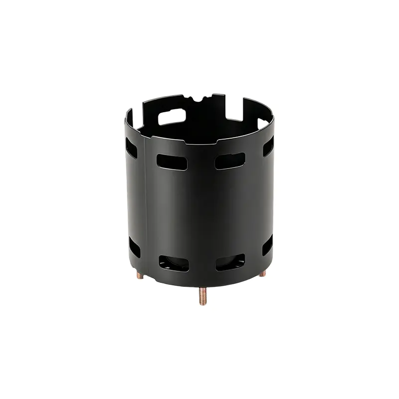
Inner Diameter 82.4 Steel Motor Housing
Product Overview
The Inner Diameter 82.4 Steel Motor Housing is manufactured for compact electric motor assemblies where dimensional control and weight reduction are essential. The body uses a thin steel wall with a nominal thickness of 1.0 mm. The internal diameter is 82.4 mm, while the external diameter is 84.4 mm, producing a compact radial envelope. Its height of 83.5 mm provides a balanced axial format suitable for motor designs that need sufficient active length without creating an excessively large overall package.
The basic dimensions are summarized below.
| Parameter | Specification | Design Significance |
|---|---|---|
| Inner diameter | 82.4 mm | Defines the available internal motor space and supports controlled component positioning |
| Outer diameter | 84.4 mm | Creates a compact external envelope for space-sensitive equipment |
| Height | 83.5 mm | Provides useful axial length while maintaining a compact form |
| Wall thickness | 1.0 mm | Reduces weight and material consumption while preserving a rigid enclosure structure |
| Material specification | SPCC / ST12 / DC01 | Supports forming, stamping, welding, and repeatable production |
| End-cover construction | Iron end covers | Provides robust closure and a practical foundation for bearing and mounting features |
| Mounting features | Four welded studs | Enables convenient installation of controllers, brackets, or related external components |
| Cooling features | Ventilation holes at both ends | Creates an axial airflow path through the motor interior |
These specifications provide a strong foundation for motor manufacturers developing lightweight and compact drive systems. The housing can be adapted to a broad range of motor architectures, subject to final validation of rotor clearance, stator dimensions, bearing specifications, fastening requirements, electrical insulation, and operating conditions.
Ultra-Thin Construction for Weight- and Space-Critical Designs
The most distinctive characteristic of this motor housing is its 1.0 mm wall thickness. A thin wall allows designers to retain a large usable inner diameter without a correspondingly large external diameter. In this product, the 82.4 mm internal diameter is contained within an 84.4 mm external diameter, giving the housing a highly efficient radial profile. This dimensional efficiency is valuable in equipment where the motor must fit into a narrow frame, a handheld enclosure, a compact transmission, or an aerodynamic structure.
Reducing housing thickness can also reduce the total mass of the motor assembly. Lower component weight may improve the handling characteristics of portable tools, reduce the power required for moving platforms, and support longer operating time in battery-powered products. In drone applications, for example, reducing motor-related weight can contribute to improved payload efficiency and flight endurance. In handheld medical or inspection devices, a lighter motor can make the product more comfortable to use for extended periods.
Weight reduction must be balanced against the need for mechanical stability. An excessively thin shell can deform during forming, welding, transportation, or assembly if the manufacturing process is poorly controlled. The design of this housing addresses that challenge through the use of formed steel, welded end covers, and an integrated enclosure structure. When the shell and end covers are correctly joined, the complete housing acts as a coordinated structural assembly rather than as an unsupported thin tube.
The use of SPCC, ST12, or DC01 material specifications further supports the manufacturing concept. These commonly used low-carbon steel grades are suitable for controlled sheet forming and fabrication. Their workability helps manufacturers produce consistent cylindrical components, while their compatibility with welding enables the end covers and associated features to be integrated into the finished housing.
Compared with a thicker steel housing, the ultra-thin design can reduce raw material usage and provide a more favorable ratio between motor interior volume and product mass. Compared with certain non-metallic housings, steel can offer higher perceived robustness, better resistance to localized mechanical damage, and useful electromagnetic shielding behavior when properly incorporated into the complete motor design. The appropriate choice still depends on the application, but the product provides a practical option for customers who need lightweight construction without moving entirely to plastic or composite materials.
Integrated End Covers and Sealed Structural Assembly
The housing is equipped with iron end covers on both ends. These covers are joined with the steel body through a combined welding process, creating an integrated enclosure. This approach is advantageous because the end covers are not merely decorative closures; they form important mechanical interfaces for bearings, mounting features, ventilation, and overall structural support.
A welded enclosure can reduce the dependence on numerous separate fasteners. Fewer loose components can simplify inventory management, reduce assembly steps, and limit the risk of missing or incorrectly installed parts. A unified structure can also improve the repeatability of the motor assembly process, especially when the welding fixtures and inspection procedures are properly controlled.
The term “sealed structure” should be interpreted according to the final application and the validated welding design. The welded housing can help create a closed and stable motor enclosure, but the actual protection rating against dust, moisture, oil, or other contaminants depends on the complete design, including joint geometry, weld quality, ventilation-hole configuration, bearing seals, cable interfaces, and any additional sealing treatment. This product provides an effective structural platform for developing a protected motor assembly, while final environmental performance should be confirmed through application-specific testing.
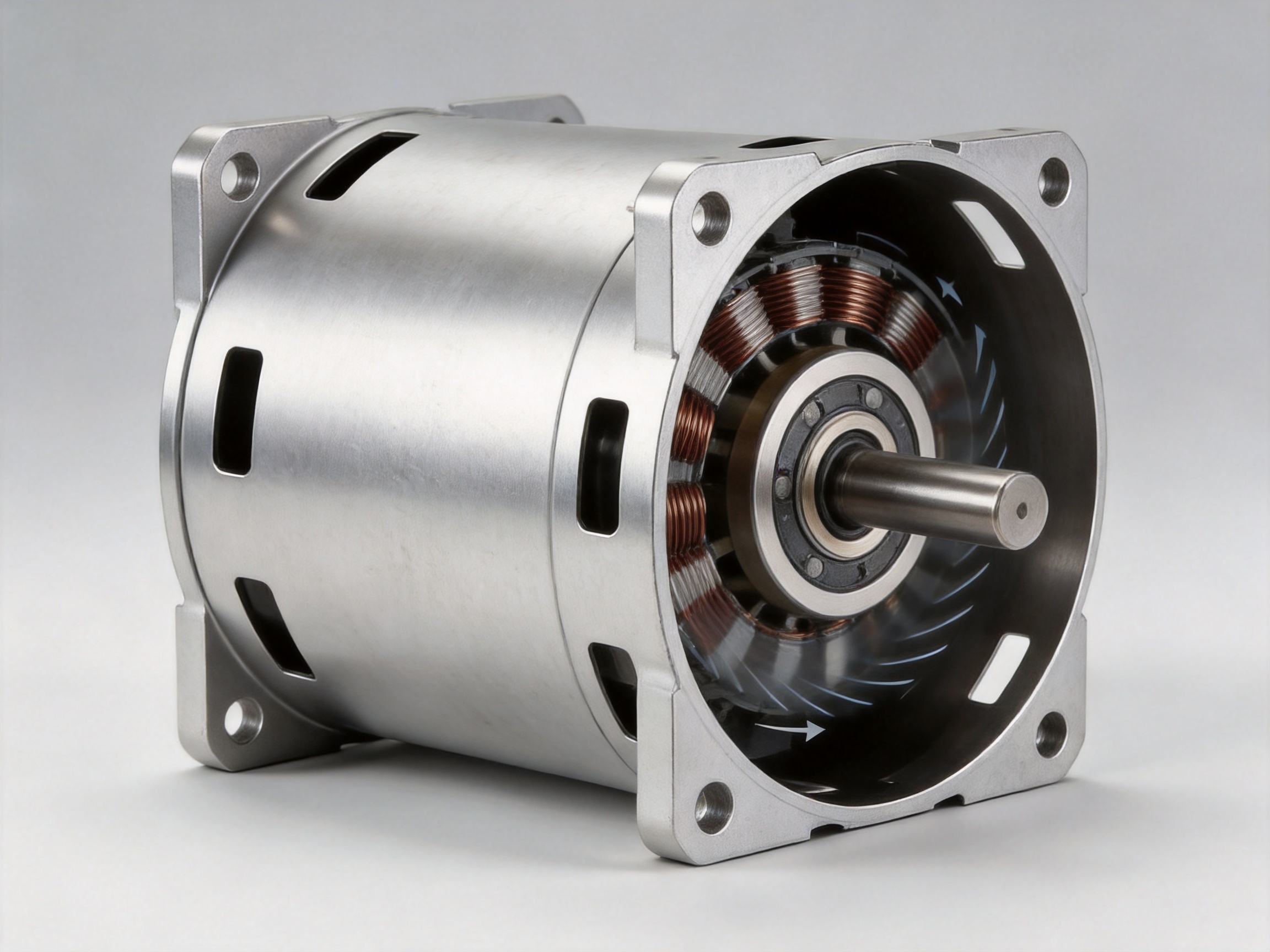
The iron end covers also provide a durable base for bearing housings. Because the bearing-supporting features are welded directly inside the end covers, the design avoids the need for a large number of independent bearing carrier components. This can reduce the number of interfaces in the motor assembly and help simplify dimensional control.
Precision Bearing Housing Integration
Bearing positioning is one of the most important mechanical considerations in a motor housing. Even a small deviation in bearing alignment can affect rotor concentricity, air-gap uniformity, vibration, noise, friction, and service life. The Inner Diameter 82.4 Steel Motor Housing incorporates precision bearing housings welded directly inside the end covers. This integrated arrangement is intended to provide accurate bearing positioning and high concentricity within the motor assembly.
Direct integration offers several potential advantages over a design that uses multiple independent bearing brackets. Every additional component and interface introduces another opportunity for dimensional variation. Separate brackets may require additional alignment procedures, fastening operations, or post-assembly adjustment. By incorporating the bearing housings into the end covers, the product can reduce the number of separate parts and make the assembly sequence more straightforward.
A simplified bearing-support structure may also benefit automated production. A motor assembler can place the bearings into prepared housing locations and proceed with a more predictable assembly flow. When combined with controlled welding fixtures, dimensional inspection, and appropriate gauge systems, the arrangement can support stable production across larger batches.
Concentricity is particularly important in compact motors because the available air gap may be limited. A properly aligned rotor must rotate without contacting the stator or housing, and the bearing system must maintain the rotor centerline under operating loads. The housing therefore contributes directly to the mechanical accuracy of the entire motor, even though it does not itself generate torque.
For customers evaluating this product, the final bearing fit and performance should be confirmed against the selected bearing type, bearing tolerance class, shaft dimensions, thermal expansion range, preload requirements, and operating speed. The welded bearing housing provides the structural basis for accurate positioning, while the complete motor design must determine the final fit and tolerance strategy.
Pre-Installed Welded Studs for Faster Mounting
Four welded studs are pre-installed on the end covers. These studs provide convenient attachment points for external controllers, mounting brackets, cable supports, shields, or other motor-related accessories. Their presence can eliminate additional drilling, tapping, or secondary fastening operations during motor assembly or equipment integration.
Pre-installed studs offer a practical advantage in high-volume manufacturing. Drilling and tapping after the housing has been formed can add process time and may introduce chip contamination, dimensional variation, or damage to protective surface treatments. By integrating the studs during the housing manufacturing process, the component can arrive at the customer ready for a more efficient installation sequence.
The stud arrangement can also support modular product design. A motor manufacturer may use the same basic housing platform with different external controllers or mounting brackets, provided that the interfaces remain compatible. This can help equipment designers develop product families with shared motor architecture while varying the surrounding electronics or mechanical attachments.
In portable power tools, welded studs may be used to secure control modules or protective brackets within a restricted enclosure. In drones, they may support a controller cover, cable guide, or structural adapter. In precision instruments, they can simplify the attachment of sensor shields or mounting components. The exact use depends on the final application, but the integrated mounting points provide flexibility without requiring customers to modify the housing.
Welded studs must be evaluated for pull-out strength, torque resistance, positional accuracy, weld integrity, and resistance to vibration. Jiangsu Yufeng Electric can use its stamping and welding capabilities to establish suitable fixtures and inspection methods for these features. Customers may also specify stud material, thread size, projection length, location, and allowable installation torque during product development.
Axial Ventilation for Improved Thermal Management
Heat is a major performance limitation in electric motors. Copper losses in the windings, iron losses in the magnetic circuit, bearing friction, and mechanical losses all generate heat. If heat is not removed efficiently, the motor may experience reduced output, accelerated insulation aging, bearing degradation, magnet damage, or protective shutdown. The Inner Diameter 82.4 Steel Motor Housing includes ventilation holes at both ends to establish an axial cooling channel through the housing interior.
With openings positioned at opposite ends, air can move through the motor along its axial direction. This arrangement supports direct airflow across internal heat-producing components, depending on the rotor design, fan effect, installation orientation, and surrounding airflow conditions. The resulting ventilation path can be especially useful in compact motors where external surface area is limited and natural heat dissipation alone may be insufficient.
Axial ventilation can also complement forced-air cooling. If a rotating element, fan, impeller, or external airflow source is incorporated into the motor system, the housing openings provide a defined route for air movement. The housing can therefore support both passive convection and application-specific forced ventilation, subject to the final opening geometry and environmental protection requirements.
The ventilation holes are a valuable feature for mobile products because they can help reduce thermal accumulation without requiring a large external cooling assembly. A lower housing temperature can support more stable motor output and help protect nearby electronic components. In handheld devices, effective airflow may allow designers to maintain a compact form while managing the heat generated during intermittent or continuous operation.
Ventilation must be designed together with contamination control. Openings can permit the entry of dust, water, fibers, or other particles if the product operates in a harsh environment. For this reason, the final equipment may require filters, protective screens, labyrinth structures, conformal coatings, or a modified ventilation arrangement. The housing provides the axial cooling concept, while the customer and manufacturer can validate the best balance between airflow and environmental protection.
Advantages Compared with Conventional Motor Housing Designs
The product offers several advantages compared with more conventional motor housing configurations. These advantages do not imply that one design is suitable for every operating condition; rather, they illustrate why an ultra-thin welded steel housing can be attractive for compact and high-volume motor applications.
Lower Material Use and Reduced Mass
A 1.0 mm wall thickness uses less material than many traditional thick-wall housings. This can reduce the component mass and support lightweight equipment design. The reduced material requirement may also improve material utilization when the manufacturing process is optimized for sheet forming and stamping.
More Efficient Use of Internal Space
The small difference between the 82.4 mm inner diameter and the 84.4 mm outer diameter provides a compact radial profile. Designers can preserve more space for active motor components or reduce the size of the surrounding product enclosure. This is particularly useful where the motor must fit inside a narrow cylindrical or near-cylindrical cavity.
Fewer Separate Components
The welded end covers and integrated bearing housings reduce the need for separate bearing carriers, cover fasteners, and supplementary structural parts. Fewer components can simplify purchasing, assembly, inventory control, and quality management.
Reduced Secondary Machining and Assembly
Because the product includes pre-installed welded studs, customers may not need to drill or tap the housing for common external attachments. This can reduce secondary operations and help prevent modification-related damage to the finished component.
Improved Alignment Potential
Directly welded bearing housings create a controlled foundation for bearing positioning. With appropriate tooling and inspection, the integrated structure can support better concentricity and more consistent rotor alignment than an assembly dependent on numerous independently positioned brackets.
Enhanced Cooling Potential
Ventilation holes at both ends create a direct axial airflow path. This can improve the opportunity for heat removal compared with a fully closed housing that relies only on external conduction and natural convection.
Good Suitability for Repeat Production
Steel sheet processing, stamping, welding, and inspection are well suited to repeatable manufacturing. Once tooling, welding parameters, and inspection standards are established, the design can support stable production quantities and consistent product quality.
Manufacturing Process Capabilities
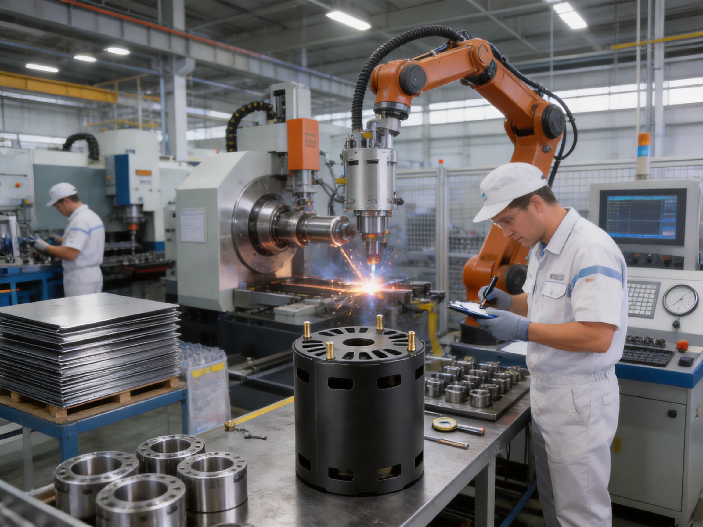
Jiangsu Yufeng Electric Co., Ltd. provides integrated manufacturing capabilities covering steel processing, stamping, welding assembly, machining, surface treatment, and final assembly. This full-process approach is important for motor housing production because the performance of the finished housing depends on the relationship between forming accuracy, weld quality, bearing position, surface condition, and final inspection.
In a fragmented supply chain, the body may be formed by one supplier, end covers produced by another, welding completed elsewhere, and machining or finishing assigned to additional vendors. While this model can work, it may create more handoffs, longer communication cycles, and greater variation between process stages. An in-house or closely coordinated process enables the manufacturer to manage the complete manufacturing route more directly.
Steel Preparation and Material Control
The process begins with suitable steel material, such as SPCC, ST12, or DC01, selected according to forming performance, strength requirements, surface condition, and customer specifications. Material identification and incoming inspection help verify thickness, flatness, surface quality, and basic conformity before production begins.
Consistent material preparation is especially important for a thin-wall housing. Variations in sheet thickness or surface condition can influence forming behavior, weld penetration, dimensional stability, and appearance. Controlled material handling helps reduce the risk of scratches, dents, contamination, or deformation before the steel reaches the forming stage.
Stamping and Forming
Stamping and forming equipment can convert flat steel sheet into the cylindrical body and related components required by the housing design. Tooling must control the body diameter, roundness, height, edge condition, and interface geometry. For a 1.0 mm wall, forming parameters and die condition require careful management to avoid wrinkling, cracking, excessive springback, or local distortion.
Accurate forming is the basis for later welding and assembly. If the cylindrical body is not sufficiently round or if its end interface is inconsistent, the end covers may not seat evenly. This can affect weld quality and ultimately influence bearing alignment, external dimensions, and motor performance.
Automated and Controlled Welding
Welding joins the body, iron end covers, bearing housings, and welded studs into an integrated assembly. Automated welding equipment can help maintain stable torch movement, energy input, weld location, and cycle time. Fixtures are used to hold parts in the intended relationship during welding, reducing movement and supporting repeatable geometry.
Thin steel requires a carefully controlled welding process. Excessive heat can cause burn-through, distortion, discoloration, or dimensional change. Insufficient heat can result in incomplete fusion or inadequate joint strength. Welding parameters therefore need to be developed according to material thickness, joint design, component fit-up, and production speed.
Weld inspection may include visual examination, dimensional checks, destructive sampling, leak-related evaluation where applicable, and other customer-specific quality controls. For critical bearing-supporting areas, the manufacturer may also inspect the position of welded bearing housings relative to the housing centerline and end-cover reference surfaces.
Machining and Precision Finishing
Although the main housing structure is formed and welded, selected areas may require machining to achieve the required fit or dimensional accuracy. Machining capabilities can support bearing seats, reference faces, mounting interfaces, or other precision features. The extent of machining depends on the product configuration and customer requirements.
Machining after welding can help correct or refine critical interfaces, but it must be carefully coordinated with the welded structure. Excessive material removal, inappropriate clamping, or uncontrolled residual stress can affect the final geometry. A capable manufacturer evaluates the sequence of forming, welding, stress stabilization, machining, cleaning, and inspection as a complete process.
Surface Treatment and Protection
Surface treatment can improve appearance, corrosion resistance, paint adhesion, or compatibility with the surrounding equipment. The appropriate treatment depends on the operating environment, storage conditions, customer requirements, and whether the housing must maintain electrical continuity for shielding or grounding purposes.
Surface treatment must also account for bearing seats, weld zones, threaded studs, ventilation holes, and assembly interfaces. Masking, cleaning, and post-treatment inspection help prevent unwanted coating buildup in locations where it could interfere with assembly or electrical performance.
Final Assembly and Inspection
Final assembly may include installation of bearings, checking of end-cover fit, verification of welded studs, cleaning of ventilation passages, and inspection of key dimensions. The complete motor housing can be evaluated using gauges, coordinate measurement equipment, optical systems, thread gauges, and other inspection instruments.
Quality control is most effective when it is integrated throughout the process rather than performed only at the end. Material inspection, first-piece approval, in-process checks, welding verification, dimensional audits, and final inspection each contribute to stable quality. This approach is especially important for thin-wall parts, where a small process deviation can affect multiple downstream features.
Engineering and Quality Strengths
Jiangsu Yufeng Electric has approximately 40 years of experience in motor housing manufacturing and has served more than 50 customers. Its engineering team has an average of more than 20 years of experience, supporting product development from early design review through mass production. This experience is valuable when a customer needs more than a standard catalog component and requires assistance with manufacturability, tolerance planning, welding design, or production optimization.
The company reports an annual production capacity of more than 5 million units. This capacity indicates the ability to support both development projects and larger-volume production programs, subject to product complexity, tooling requirements, scheduling, and customer quality standards. A manufacturer with substantial production experience can often identify potential issues earlier, including difficult forming areas, weld distortion risks, inaccessible inspection points, or assembly conflicts.
Engineering support is particularly important for this ultra-thin housing because the product combines several precision-related features. The 1.0 mm wall must be formed without unacceptable deformation. The end covers must be positioned consistently. Bearing housings must remain accurately aligned. Welded studs must meet location and strength requirements. Ventilation openings must be produced without compromising the structural or environmental objectives of the design.
Full-process manufacturing also improves communication. When a customer requests a change to the inner diameter, end-cover profile, stud position, ventilation pattern, material grade, surface treatment, or bearing interface, the manufacturer can review the effect across forming, welding, machining, assembly, and inspection. This integrated perspective supports faster technical response and reduces the risk that an isolated change will create an unexpected problem in another process.
Application Suitability
Drone Motors
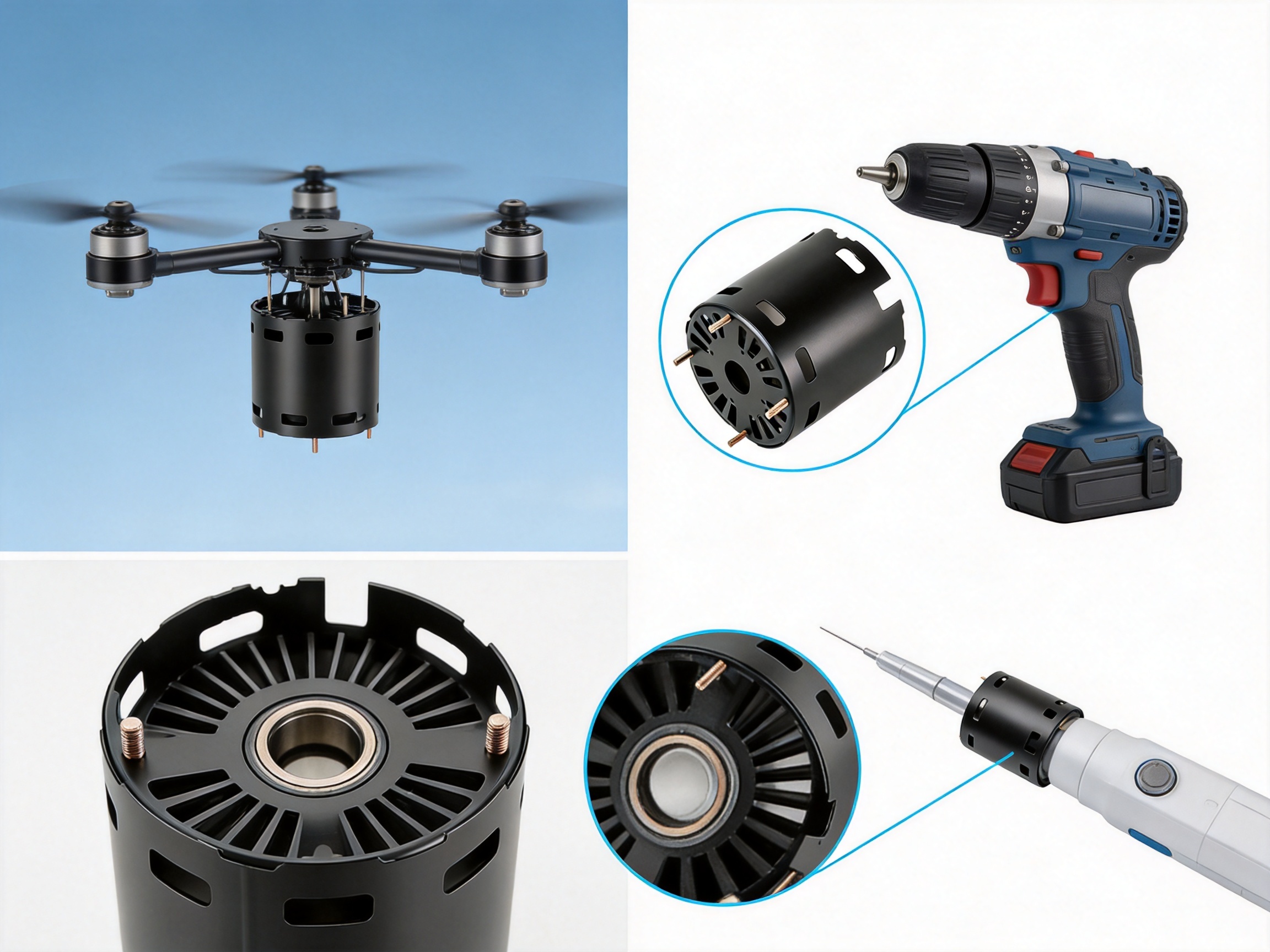
Drone propulsion systems are highly sensitive to weight, balance, thermal performance, and dimensional consistency. The lightweight steel structure can help reduce motor mass while maintaining a durable enclosure. The compact external diameter supports efficient integration into a propulsion module, and the axial ventilation path can assist with heat removal during sustained operation.
Drone applications also require careful attention to vibration, high rotational speed, weather exposure, and contamination. Before use in a flight-critical system, the complete motor should be validated for rotor balance, bearing life, vibration, temperature rise, environmental exposure, and structural fatigue. The housing provides a strong starting point for such development, but flight-system qualification remains essential.
Portable Power Tools
Portable drills, grinders, cutters, screwdrivers, and other battery-powered tools benefit from compact and lightweight motor assemblies. A lighter housing can improve operator comfort and reduce overall tool weight. The welded studs can support the attachment of controllers, protective components, or internal brackets, while the ventilation openings can help manage heat during repeated operation.
Power tools may experience impact, vibration, dust, and rapid load changes. The final tool design may therefore require protective airflow structures, dust-management features, robust bearing selection, and additional testing. The steel housing’s integrated structure can contribute to durability, but the complete tool must be evaluated as a system.
Medical Handheld Devices
Medical handheld equipment often requires low noise, compact packaging, predictable thermal behavior, and comfortable handling. The housing’s lightweight format and integrated bearing support can help designers develop a small motor assembly with fewer internal parts. Ventilation and surface treatment must be selected carefully according to cleaning procedures, hygiene requirements, and the device’s environmental classification.
For medical applications, material traceability, process validation, cleanliness, and documentation may be as important as mechanical performance. The manufacturer can work with customers to define inspection records, material documentation, process controls, and acceptance criteria appropriate to the intended device.
Precision Instruments
Analytical instruments, optical devices, laboratory equipment, and compact automation systems may require stable motor positioning and low vibration. The integrated bearing housings and controlled welded structure can support accurate rotor alignment. The compact profile also leaves more space for sensors, control boards, optical paths, or other precision assemblies.
In precision applications, customers should define acceptable runout, concentricity, vibration, noise, bearing preload, and thermal drift requirements at the beginning of the project. The housing can then be engineered and inspected according to the actual performance target rather than only nominal dimensional values.
Household Appliances and Industrial Drives
Although the product is particularly suitable for mobile and handheld applications, the manufacturing platform also serves broader markets such as household appliances, industrial drives, new energy vehicles, and special equipment. A customized version of the housing may be considered for auxiliary motors, compact actuators, fans, pumps, or other equipment requiring steel construction and integrated fabrication.
Customization and Product Development
The standard dimensions of this product provide a useful starting point, but motor manufacturers often require customized features. Potential customization areas include end-cover geometry, bearing-seat dimensions, stud size and location, ventilation-hole quantity and shape, mounting references, surface treatment, material specification, and packaging method.
Customization should begin with a review of the complete motor assembly. Important inputs include the stator outer diameter, rotor diameter, axial stack length, shaft dimensions, bearing type, air-gap requirements, winding temperature, expected speed, mounting orientation, environmental exposure, and controller arrangement. These factors determine whether the standard 82.4 mm inner diameter and 83.5 mm height are suitable or whether an adjusted design is required.
A structured development process can include drawing review, manufacturability analysis, prototype production, dimensional inspection, trial assembly, functional testing, process validation, and mass-production approval. Early prototype testing helps identify interference, thermal issues, weld distortion, bearing-fit concerns, or installation difficulties before the design enters full production.
Customers may also benefit from design-for-manufacturing recommendations. For example, the manufacturer may suggest modifications to improve material utilization, reduce weld distortion, simplify tooling, increase inspection accessibility, or improve the consistency of a stud or bearing interface. Such recommendations can lower total production cost even when the initial purchase price is not the only consideration.
Installation and Validation Considerations
Before installation, the housing should be inspected for damage, deformation, contamination, blocked ventilation holes, damaged threads, or irregularities in the bearing-support areas. The inner diameter, end-cover condition, stud position, and relevant reference dimensions should be checked according to the approved drawing or inspection plan.
Bearings should be installed using appropriate tools and loading methods. Force should be applied to the correct bearing ring, and impact should not be transmitted through the rolling elements. Improper installation can damage the bearing or alter the alignment that the housing is designed to maintain.
The assembled motor should be evaluated for rotor freedom, air-gap clearance, axial movement, radial runout, vibration, noise, current draw, temperature rise, and operating stability. Ventilation performance should be reviewed under the actual installation conditions because surrounding covers, filters, cable routing, and mounting orientation can influence airflow.
Where the housing is used in a sealed or semi-protected product, environmental testing should reflect the intended application. Relevant evaluations may include dust exposure, humidity, water splash, corrosion, thermal cycling, vibration, shock, and endurance operation. The correct test program depends on the final product and cannot be determined solely from the housing dimensions.
Purchasing and Supply Considerations
For purchasing teams, the main value of this motor housing lies in the combination of product design and manufacturing capability. A supplier should be evaluated not only by nominal dimensions, but also by process control, welding consistency, engineering responsiveness, inspection capacity, production scalability, and ability to support design changes.
Important procurement documents may include approved drawings, material specifications, dimensional inspection reports, welding standards, surface-treatment requirements, packaging instructions, and quality acceptance criteria. For recurring orders, customers may also establish first-article inspection procedures, process-change notification requirements, traceability expectations, and statistical quality targets.
Packaging is important for thin-wall components because improper stacking or excessive external force can cause deformation. Protective separators, suitable cartons, corrosion-inhibiting materials, and controlled handling can help ensure that the housing reaches the customer in the intended condition. Packaging design should also protect welded studs, bearing interfaces, ventilation openings, and finished surfaces.
Why Choose an Integrated Steel Housing Solution?
An integrated steel housing solution can provide benefits beyond the individual component. It allows the motor designer to address structural support, bearing positioning, mounting, ventilation, and manufacturability through one coordinated part. This can reduce the number of design interfaces and make the motor easier to assemble and service.
The Inner Diameter 82.4 Steel Motor Housing is especially attractive when the customer needs a thin, lightweight, and compact enclosure but still values the mechanical stability of steel. Its iron end covers provide practical structural interfaces, while welded bearing housings support a more direct alignment strategy. The four welded studs add installation flexibility, and the end ventilation holes contribute to an efficient cooling concept.
Compared with a basic tube that requires multiple separately purchased covers, bearing brackets, mounting pieces, and machining operations, this product offers a more complete starting point. Compared with an overly heavy steel enclosure, it offers improved weight efficiency. Compared with a non-metallic solution, it provides a steel-based structure that may better suit applications requiring durability, heat tolerance, or electromagnetic enclosure characteristics.
The final selection should always be based on technical validation, but the combination of compact geometry, low wall thickness, integrated welding, bearing support, mounting studs, and axial ventilation gives this housing a strong value proposition for modern motor development.
Frequently Asked Questions
What are the main dimensions of the motor housing?
The housing has an inner diameter of 82.4 mm, an outer diameter of 84.4 mm, a height of 83.5 mm, and a nominal wall thickness of 1.0 mm.
Which materials are specified for the housing?
The listed material specifications are SPCC, ST12, and DC01. The final grade should be confirmed according to the approved product drawing, forming requirements, welding process, surface treatment, and application conditions.
Why is the 1.0 mm wall thickness beneficial?
The thin wall reduces material usage and component weight while preserving a large internal diameter within a compact external envelope. This is useful for drones, portable tools, handheld devices, and other applications where space and mass are limited.
Does the housing include end covers?
Yes. Iron end covers are provided on both ends and are joined to the housing body through a combined welding process to create an integrated structural enclosure.
Are bearing housings included?
Yes. Precision bearing housings are welded directly inside the end covers. This arrangement is intended to support accurate bearing positioning and high concentricity while reducing the need for separate bearing-support components.
What is the purpose of the four welded studs?
The four pre-installed welded studs provide attachment points for external controllers, mounting brackets, cable supports, protective parts, or other accessories. They can eliminate additional drilling and tapping during customer assembly.
How does the housing support motor cooling?
Ventilation holes at both ends create an axial airflow channel through the housing interior. This can support natural convection or forced-air cooling, depending on the motor design and surrounding equipment.
Is the housing suitable for high-speed motors?
It may be suitable for high-speed motor designs, but the complete assembly must be validated for rotor balance, bearing performance, structural strength, vibration, air-gap control, temperature rise, and operating speed. The housing specification alone does not establish a maximum motor speed.
Can the design be customized?
Customization may be available for dimensions, end-cover geometry, bearing interfaces, stud positions, ventilation patterns, surface treatment, material requirements, and other features. Customers should provide application requirements and motor assembly drawings for engineering review.
Can the ventilation openings be modified?
Ventilation features can potentially be adjusted, but changes should be evaluated for airflow, structural strength, contamination protection, noise, and manufacturing feasibility. Any modification should be included in an approved drawing and validated through testing.
What manufacturing processes are available?
The manufacturer provides integrated capabilities including stamping, forming, welding assembly, machining, surface treatment, inspection, and final assembly. This supports coordinated control from steel processing through finished motor housing delivery.
What industries can use this product?
Potential applications include drone motors, portable power tools, medical handheld equipment, precision instruments, household appliances, industrial drives, new energy vehicle components, and special equipment. Suitability depends on the final mechanical, thermal, electrical, and environmental requirements.
How should the housing be evaluated before mass production?
Evaluation may include dimensional inspection, trial assembly, bearing-fit verification, rotor clearance checks, vibration and noise testing, temperature-rise testing, weld inspection, mounting-strength testing, and environmental testing appropriate to the final product.
What makes the manufacturer suitable for custom motor housing projects?
Jiangsu Yufeng Electric combines approximately 40 years of motor housing experience with stamping, automated welding, machining, surface treatment, inspection equipment, and engineering support. The company also reports service to more than 50 customers and annual production capacity exceeding 5 million units.
Conclusion
The Inner Diameter 82.4 Steel Motor Housing is a compact and carefully integrated solution for motor applications where low weight, efficient space utilization, reliable alignment, convenient mounting, and thermal management are important. Its 1.0 mm steel wall provides an ultra-thin structure, while the 82.4 mm inner diameter and 84.4 mm outer diameter create an efficient radial package.
The welded iron end covers transform the basic shell into a complete structural housing. Directly welded bearing housings support accurate positioning and high concentricity. Four welded studs simplify the attachment of controllers and brackets. Ventilation holes at both ends establish an axial cooling path that can help manage heat in compact motor assemblies.
Its advantages are strengthened by the manufacturer’s integrated production capabilities. Stamping, welding, machining, surface treatment, assembly, and inspection can be coordinated within one manufacturing system. Supported by experienced engineers, established production capacity, and long-term motor housing expertise, the company can provide both standard products and customized development support.
For motor manufacturers and equipment designers seeking a lightweight steel enclosure with integrated functional features, this housing offers a strong platform for development. Final performance should be confirmed through application-specific engineering and testing, but the product’s combination of thin-wall efficiency, structural integration, bearing support, mounting convenience, and axial ventilation makes it a practical choice for next-generation compact motor systems.
References
1. Product specification information for the Inner Diameter 82.4 Steel Motor Housing, including dimensional and material data.
2. General engineering principles for electric motor housing design, bearing alignment, structural welding, and thermal management.
3. General technical references for SPCC, ST12, and DC01 low-carbon steel sheet materials and forming applications.
4. Manufacturing process references covering stamping, thin-sheet forming, automated welding, machining, surface treatment, and dimensional inspection.
5. General application engineering practices for compact motors used in drones, portable power tools, handheld medical equipment, precision instruments, household appliances, and industrial drives.

 Previous