

 English
 Español
Content
- 1 Product Overview
- 2 Why Heavy-Wall Construction Matters
- 3 Integrated Thermal Management
- 4 Material Selection: 20# Steel
- 5 Advantages Compared with Conventional Motor Housings
- 6 Manufacturing Process Capabilities
- 7 Quality and Production Reliability
- 8 Application Areas
- 9 Installation and Engineering Considerations
- 10 Customization and Project Support
- 11 Why Choose an Integrated Motor Housing Manufacturer?
- 12 Packaging, Delivery, and Long-Term Supply
- 13 Frequently Asked Questions
- 13.1 What is the inner diameter of this motor housing?
- 13.2 What is the height of the housing?
- 13.3 What is the outer diameter?
- 13.4 How thick is the housing wall?
- 13.5 What material is used?
- 13.6 How does the exterior thread design improve cooling?
- 13.7 Is this product suitable for high-load motors?
- 13.8 Can the housing be customized?
- 13.9 What manufacturing processes are available?
- 13.10 Which industries can use this housing?
- 13.11 Does a heavy-wall housing guarantee longer motor life?
- 13.12 What should be checked before placing an order?
- 14 Conclusion
- 15 References
- 16 Product: Inner Diameter 113 Heavy-Wall Motor Housing
Motor housing performance directly affects the reliability, service life, thermal stability, and mechanical safety of an electric motor. Although a housing is sometimes viewed as a passive enclosure, it performs several essential engineering functions at the same time. It supports and protects internal components, helps maintain dimensional alignment, resists vibration and impact, transfers heat away from the motor, and contributes to the overall strength of the finished assembly. For demanding motors operating under high torque, high load, or frequent cycling, the housing must offer much more than basic containment.
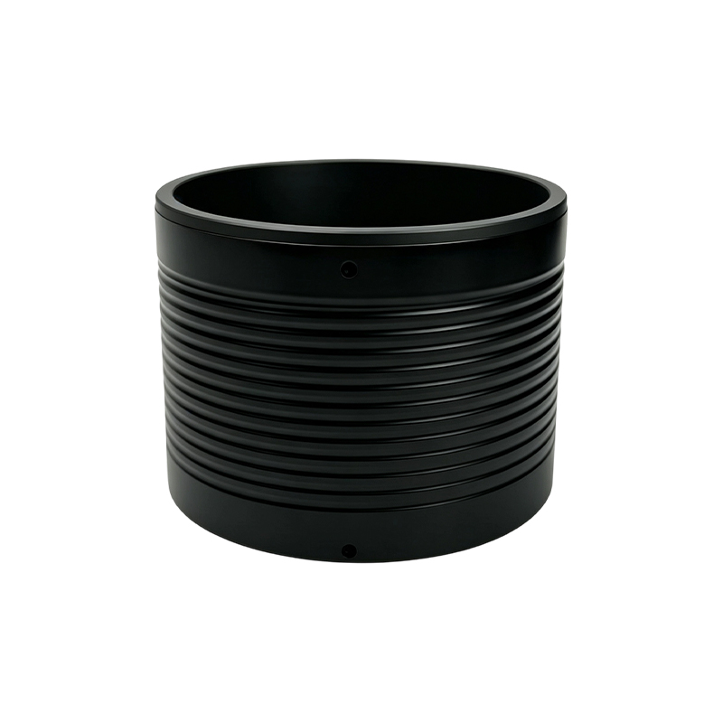
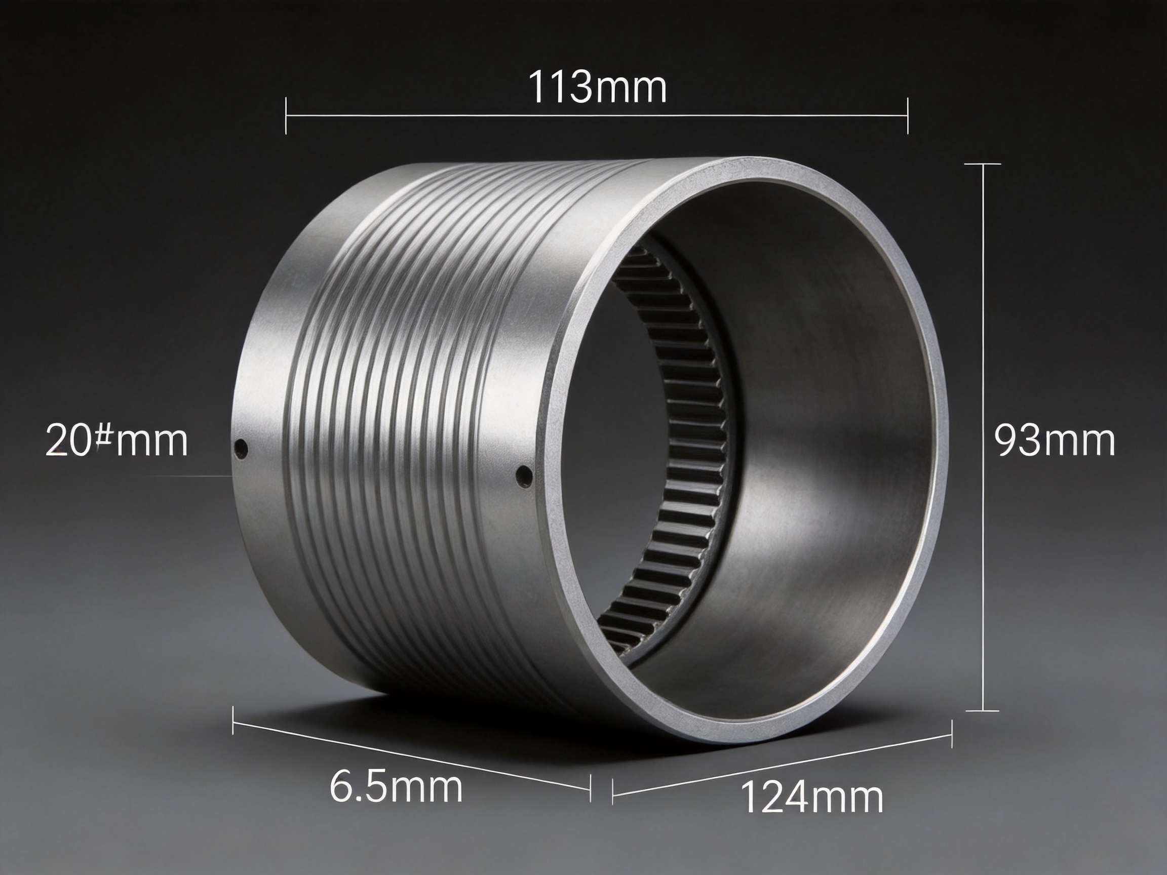
The Inner Diameter 113 Heavy-Wall Motor Housing is a steel tube motor housing developed for applications requiring structural rigidity, dependable protection, and improved heat dissipation. It has a nominal inner diameter of 113 mm, a height of 93 mm, an outer diameter of 124 mm, and a wall thickness of 5.5 mm. Manufactured from 20# steel, this housing combines a robust material specification with a carefully engineered geometry intended to withstand demanding operating conditions.
Its heavy-wall construction provides an effective balance between strength and manufacturability. The 5.5 mm wall supports resistance to deformation, impact, and vibration while maintaining a practical cylindrical form for motor assembly. The exterior also incorporates a dedicated heat dissipation thread design. These external threads enlarge the effective heat-transfer area and create natural air-guiding grooves that can improve the movement of air around the housing.
Produced by Jiangsu Yufeng Electric Co., Ltd., the housing benefits from an integrated manufacturing system covering steel processing, stamping, welding assembly, machining, inspection, and surface treatment. This full-process capability enables the manufacturer to control important production variables internally, support customized development, and maintain consistent quality from initial material preparation through finished delivery.
Inner Diameter 113 Heavy-Wall Motor Housing
Product Overview
The Inner Diameter 113 Heavy-Wall Motor Housing is designed as a protective and structural shell for electric motor assemblies. Its principal purpose is to provide a precise cylindrical space in which internal motor parts can be installed and supported. Depending on the final motor design, these internal parts may include the stator, rotor-related components, bearings, end covers, insulation systems, terminals, and other supporting elements.
The housing’s 113 mm inner diameter establishes the primary installation envelope. The 93 mm height defines the axial body dimension, while the 124 mm outer diameter reflects the basic external cylindrical size before considering any local features or thread geometry. With a 5.5 mm wall thickness, the product is substantially more robust than a thin-wall enclosure intended only for light-duty protection.
The housing is classified as a steel tube motor housing. This classification reflects its cylindrical tube-based construction and its suitability for motors that require a continuous, strong, and dimensionally controlled shell. The tube format can support efficient material flow, repeatable production, and reliable concentricity when suitable forming, machining, and inspection procedures are applied.
The product identification code is ID113021. This identification helps distinguish the specified configuration from other motor housing sizes and designs. In practical procurement and engineering work, a clear product code is important because motor housings are often manufactured in multiple diameters, heights, materials, wall thicknesses, and feature arrangements.
Key Product Specifications
| Specification | Value |
|---|---|
| Product type | Heavy-wall steel tube motor housing |
| Product identification | ID113021 |
| Inner diameter | 113 mm |
| Height | 93 mm |
| Outer diameter | 124 mm |
| Wall thickness | 5.5 mm |
| Material specification | 20# steel |
| Exterior feature | Heat dissipation thread design |
| Application category | Electric motor housing and related motor assemblies |
These specifications should be evaluated together rather than individually. The relationship between inner diameter, outer diameter, and wall thickness indicates a substantial steel section capable of supporting high structural loads. The height provides the axial envelope required by the intended motor design, while the exterior thread feature improves the thermal function of the cylindrical body.
Why Heavy-Wall Construction Matters
Motor housings experience a combination of mechanical and thermal stresses during operation. Internal electromagnetic forces can produce vibration, while rotating components generate dynamic loads. Starting, stopping, reversing, and sudden changes in torque can place additional stress on the housing and on the interfaces between the housing and other motor components. In industrial or transportation-related environments, external shocks and continuous vibration may further increase the demand placed on the enclosure.
A heavy-wall steel structure helps address these requirements by increasing section strength and improving resistance to local deformation. When a housing deforms, even slightly, it can affect the alignment of the stator, rotor, bearings, or end covers. Such changes may increase friction, create uneven air gaps, raise noise levels, accelerate wear, or reduce motor efficiency. A rigid housing helps preserve the intended geometry during assembly and operation.
The 5.5 mm wall thickness provides a strong structural foundation for the housing. Compared with a lighter enclosure, the heavy-wall design can offer greater resistance to denting and distortion during handling, assembly, and service. It also provides more material around the cylindrical body to support machining, joining, mounting, and interface features when those operations are included in the customer’s final design.
Heavy-wall construction can also improve perceived product stability. A rigid housing is less likely to respond excessively to vibration and impact, helping create a more secure platform for internal motor components. This is particularly relevant for motors exposed to repeated starts, high torque, variable loads, or installation environments in which mechanical disturbances cannot be completely eliminated.
Resistance to Deformation
Deformation resistance is one of the most important advantages of a robust motor housing. A cylindrical shell must maintain its roundness and axial geometry within the limits required by the motor assembly. If the shell becomes oval, bowed, or locally dented, the internal components may no longer be supported evenly.
The substantial wall section of this product helps reduce the likelihood of such changes under normal mechanical loads. The use of 20# steel provides a practical material base for a strong, machinable, and weldable structure. When combined with controlled manufacturing and inspection, the material and geometry can support repeatable production of housings for demanding motor applications.
Impact and Vibration Protection
Electric motors may be installed in equipment that experiences transportation vibration, machine vibration, switching shocks, or periodic impacts. The housing serves as the first line of defense for the internal motor assembly. Its heavy-wall design provides a durable barrier that can help reduce the risk of damage caused by external mechanical disturbances.
A strong housing does not eliminate the need for proper motor mounting or vibration control. However, it provides a more resilient enclosure and can reduce the sensitivity of the assembly to handling and operating conditions. This is a practical advantage over lightweight housings that may be more vulnerable to dents, distortion, or fatigue when used outside low-load environments.
Integrated Thermal Management
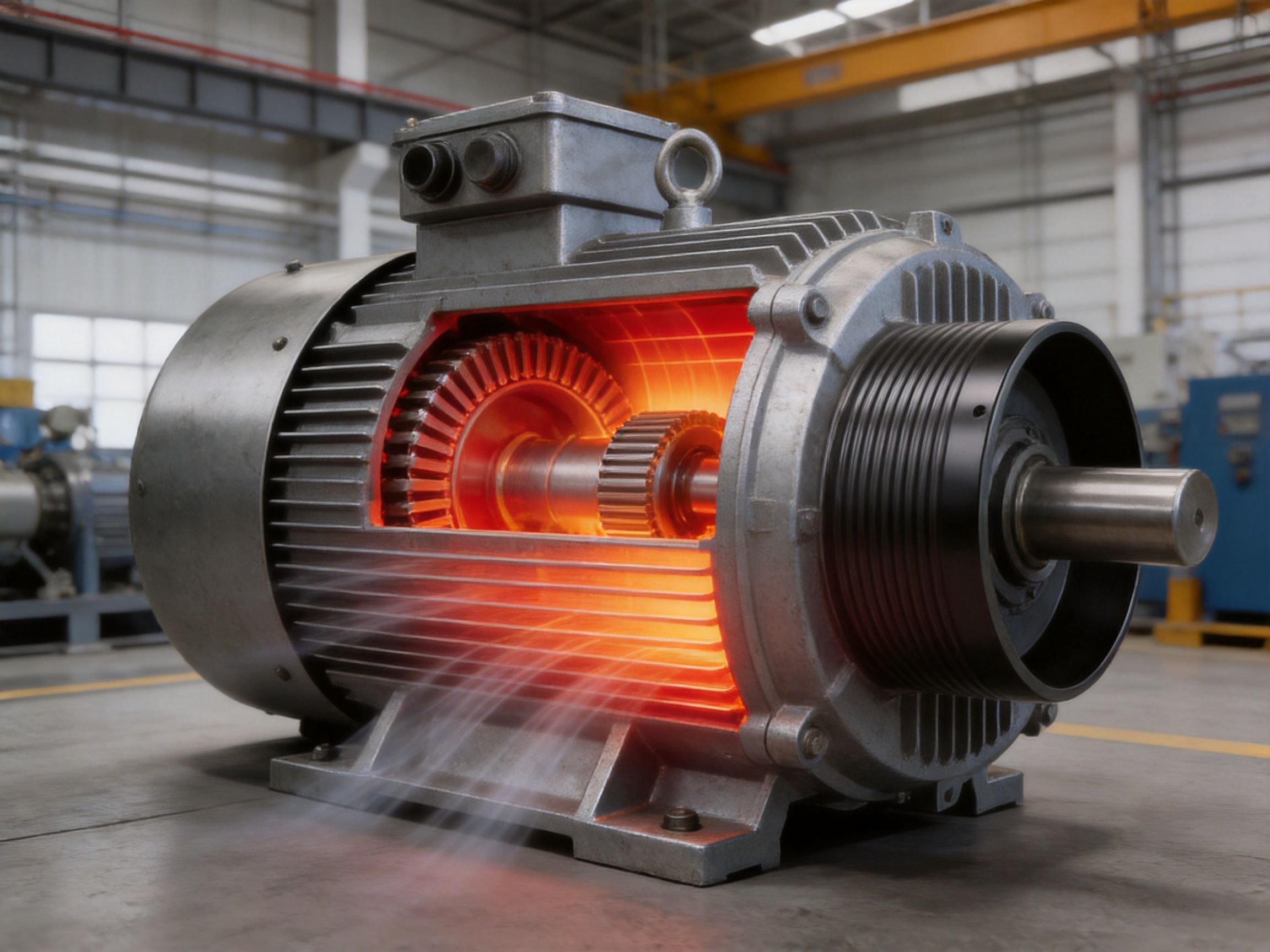
Thermal management is central to motor reliability. During operation, electrical resistance, magnetic losses, mechanical friction, and switching activity generate heat. If this heat is not removed efficiently, the motor temperature can rise. Excessive temperature may shorten insulation life, accelerate lubricant degradation, affect bearing performance, and reduce the motor’s ability to operate continuously at its intended load.
The Inner Diameter 113 Heavy-Wall Motor Housing addresses heat management through an exterior heat dissipation thread design. The thread structure increases the area exposed to the surrounding air. A larger external surface provides more opportunity for heat to travel from the steel housing into the environment through convection and radiation.
The thread grooves also create natural air-guiding channels. As air moves around the motor, these channels can help direct airflow along the housing surface and improve contact between the heated metal and the surrounding air. The exact thermal performance will depend on motor power, installation orientation, airflow velocity, ambient temperature, mounting configuration, and the final surface finish. Nevertheless, the geometry provides a purposeful thermal feature rather than relying only on a smooth cylindrical wall.
Expanded Heat-Transfer Surface
A smooth cylinder offers a relatively limited external area for a given diameter and height. Adding external threads or ribs increases the surface area without requiring a major increase in the motor’s basic internal envelope. This is useful when the designer must preserve the 113 mm inner diameter while seeking better heat dissipation.
The increased surface area can help spread heat over a larger region of the housing. Instead of concentrating thermal energy on a simple outer wall, the threaded profile creates additional metal-air interfaces. This can support faster heat exchange, especially when the motor is installed in an environment with natural or forced airflow.
The thread feature may also contribute to more consistent thermal distribution. By extending along the housing exterior, the grooves and raised portions help distribute the available heat-transfer area around the circumference. A more evenly distributed surface can be beneficial in motor designs where heat is generated across a broad internal region.
Airflow Guidance
The grooves formed by the external thread design act as natural channels for air movement. Under natural convection, warm air tends to rise and cooler air moves in to replace it. Under forced airflow, the grooves can provide additional pathways around the housing surface. The result is a housing exterior designed to participate actively in thermal management.
Airflow performance should always be considered together with the final installation. A motor surrounded by closely packed structures may not achieve the same heat dissipation as a motor installed with sufficient clearance. Designers should evaluate the housing in the complete motor and equipment configuration, considering fan placement, ventilation openings, ambient conditions, and expected duty cycle.
Support for Continuous Operation
By helping conduct and dissipate heat, the housing can reduce temperature rise during operation. Lower temperature rise may support longer periods of continuous running and help protect the motor’s insulation system. It may also reduce thermal stress on adjacent components and contribute to more stable motor performance.
The housing is not a substitute for correct electrical design, suitable insulation materials, adequate bearings, or appropriate overload protection. However, it is an important part of the complete thermal system. A housing that combines structural strength with a dedicated cooling surface offers a more comprehensive solution than an enclosure designed solely for mechanical containment.
Material Selection: 20# Steel
The product uses 20# steel as its specified material. This material is commonly selected for applications requiring a practical combination of strength, formability, weldability, machinability, and cost control. It provides a suitable foundation for a motor housing that must undergo forming or tube-related processing, machining, assembly, and potentially welding operations.
Material selection affects every stage of production. The steel must be compatible with the chosen forming method and must maintain sufficient dimensional stability during manufacturing. It must also support machining of interfaces and allow reliable joining where the final motor assembly requires welded or attached components.
For a heavy-wall housing, material consistency is especially important. Variations in chemical composition, thickness, hardness, or surface condition can influence forming behavior, machining performance, welding quality, and final dimensional accuracy. An experienced manufacturer can reduce these risks through incoming material control, process monitoring, and inspection at multiple stages.
The use of 20# steel also supports practical customization. Depending on the customer’s requirements, the housing may be developed with changes to height, diameter, interface geometry, mounting details, or surface treatment. Final material and process decisions should be confirmed through engineering review and application-specific validation.
Balance of Strength and Manufacturability
One potential disadvantage of extremely hard or highly specialized materials is increased manufacturing complexity. They may require more demanding forming equipment, specialized tooling, slower machining, or more complex welding procedures. A well-selected engineering steel can provide strong performance while keeping production manageable and repeatable.
The specified steel is therefore appropriate for a product intended to combine heavy-wall rigidity with full-process manufacturing. The material supports the production of a robust housing without making the product unnecessarily difficult to process or customize.
Advantages Compared with Conventional Motor Housings
The Inner Diameter 113 Heavy-Wall Motor Housing has several characteristics that can distinguish it from conventional thin-wall or smooth-surface motor housings. These advantages should be considered in relation to the intended operating environment and the customer’s complete motor design.
Greater Structural Rigidity
The 5.5 mm wall thickness provides a stronger section than many lightweight housings. This can improve resistance to impact, vibration, and deformation. For high-torque or high-load motors, the added rigidity may help preserve internal alignment and reduce the risk of housing-related mechanical instability.
Improved Mechanical Protection
A heavy steel shell provides a durable barrier around sensitive internal components. It can help protect the motor from external contact, handling damage, and operating vibration. This is valuable in industrial drives, equipment systems, special machinery, and other applications where a motor may be exposed to demanding service conditions.
Purpose-Built Heat Dissipation
Many basic housings use a smooth external surface with no dedicated thermal enhancement. This product incorporates external thread geometry intended to increase heat-transfer area and guide air. The design therefore combines mechanical enclosure and thermal management in one integrated component.
Controlled Dimensional Envelope
The clearly defined 113 mm inner diameter and 93 mm height allow the housing to be incorporated into a specific motor architecture. A known inner diameter is particularly important for stator installation, internal clearances, and component alignment. The 124 mm outer diameter and 5.5 mm wall thickness further establish the external packaging requirements.
Suitability for Integrated Production
The product is manufactured by a supplier with capabilities covering stamping, welding assembly, machining, and surface treatment. This can be an advantage over sourcing different processes from multiple vendors. Integrated production can simplify technical communication, shorten coordination cycles, and improve responsibility for final product quality.
Potential for Custom Development
Motor housings are rarely universal components. Different customers may require changes to height, mounting features, connection interfaces, surface protection, or internal fit. A manufacturer with engineering and production resources can adapt the basic housing concept to specific requirements while maintaining control over manufacturing feasibility.
Manufacturing Process Capabilities
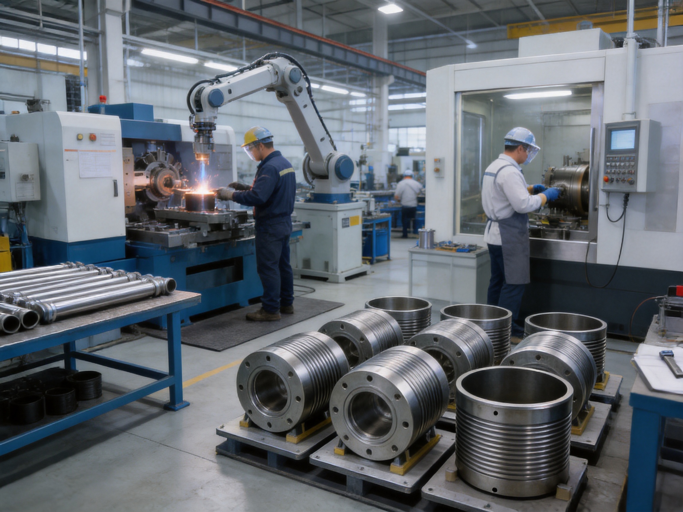
Jiangsu Yufeng Electric Co., Ltd. operates as a professional motor housing manufacturer with integrated capabilities in research and development, steel processing, stamping, welding assembly, machining, surface treatment, and inspection. This combination is important because housing quality depends not on one operation alone, but on the relationship between all operations.
Engineering and Product Development
Product development begins with understanding the motor’s functional requirements. Engineers must consider inner diameter, height, wall thickness, outer profile, mounting conditions, heat dissipation, assembly sequence, material behavior, and expected loads. A housing design that looks simple in isolation may require careful evaluation when integrated with stators, end covers, bearings, fasteners, and electrical components.
An experienced engineering team can review customer drawings, identify production risks, suggest practical modifications, and support the transition from prototype to mass production. The manufacturer reports an engineering team with an average of more than 20 years of experience, providing a strong foundation for application-oriented development and process problem-solving.
Steel Processing
Steel processing establishes the foundation for the finished housing. Material must be prepared to the required dimensions and condition before forming, machining, welding, or other operations. Proper preparation can help limit defects, reduce material waste, and maintain consistent wall geometry.
For a heavy-wall component, steel processing must account for both mass and dimensional control. A thick section can provide strength, but it may also require suitable equipment and process parameters to achieve the required shape without unwanted distortion. Controlled preparation and handling support stable downstream production.
Stamping and Forming
Stamping and forming operations can be used to create repeatable features and profiles in steel components. Proper tooling design is essential for maintaining dimensional consistency, especially when a product includes mounting details, edges, openings, or other formed features.
Tooling must be matched to the material specification, wall thickness, product geometry, and expected production volume. A stable stamping process can improve repeatability and reduce variation between batches. It can also support efficient large-scale manufacturing when the design is standardized and the tooling has been properly validated.
Automated Welding Equipment
Welding may be required when the housing is combined with additional structural or functional components. Automated welding equipment can help improve consistency in weld location, speed, penetration, and appearance. Automation is especially valuable for repeated production because it can reduce variation associated with manual positioning and operator fatigue.
Welding quality affects both structural integrity and dimensional accuracy. Excessive heat input may cause distortion, while insufficient joining quality may reduce strength or create leakage and corrosion risks. Process control, fixture design, weld inspection, and suitable post-weld procedures are therefore important parts of the manufacturing system.
Machining Facilities
Machining is used to produce precise interfaces, correction surfaces, mounting features, bores, grooves, and other details required by the motor assembly. Even when the main body is created through tube processing or forming, machining may be essential for achieving the final dimensional relationships.
Machining accuracy is particularly important around interfaces that affect concentricity, bearing seating, end-cover installation, or stator positioning. Controlled machining can help the housing meet the tolerances required by the motor design and reduce assembly difficulty.
Surface Treatment
Surface treatment can improve the housing’s resistance to corrosion, handling damage, and environmental exposure. The appropriate treatment depends on the customer’s operating conditions, appearance requirements, storage conditions, and compatibility with other motor components.
Surface preparation must be controlled carefully. Cleaning, treatment, drying, coating, and curing conditions can all influence final performance. A manufacturer that controls surface treatment within its broader production system can coordinate this step with machining, assembly, inspection, and packaging requirements.
Inspection and Quality Control
Inspection instruments support verification of dimensions, geometry, surface condition, and process results. For a housing with a defined inner diameter, outer diameter, height, and wall thickness, measurement is necessary to confirm conformity with the specified design.
Inspection may include dimensional checks, visual examination, weld evaluation where applicable, surface inspection, and verification of key interfaces. The precise inspection plan should be established according to product drawings, customer requirements, production volume, and application risk.
Quality and Production Reliability
Production reliability depends on repeatable processes rather than final inspection alone. A strong quality system begins with clear drawings, controlled materials, qualified equipment, suitable tooling, trained personnel, and documented operating procedures. It continues through in-process checks and final verification.
For motor housings, dimensional consistency is particularly important because the component is part of a tightly integrated assembly. A housing that varies from batch to batch may require adjustment of the stator, end cover, bearing arrangement, or assembly tooling. Stable production reduces these disruptions and supports predictable motor performance.
The manufacturer’s integrated production model provides a single technical chain from development to delivery. This can make it easier to identify the root cause of a problem. If a dimensional issue is found after machining, for example, the team can review the preceding material, forming, welding, fixture, and machining steps within one coordinated system.
Jiangsu Yufeng Electric Co., Ltd. reports 40 years of experience in motor housing manufacturing, service to more than 50 customers, and annual production capacity exceeding 5 million units. These figures indicate an established production background and experience with repeated manufacturing at commercial scale. Capacity alone does not guarantee suitability for every project, but it can provide valuable support for customers seeking a stable long-term supply partner.
Application Areas
The housing can be considered for electric motors used in household appliances, industrial drives, new energy vehicles, and special equipment. The final suitability depends on the motor’s electrical rating, duty cycle, load profile, installation environment, thermal requirements, and interface design.
Household Appliances
Household appliance motors may require compact packaging, reliable operation, low noise, and efficient heat management. A rigid housing can support consistent internal alignment, while the external thread design may assist thermal performance where the available airflow is limited.
Appliance manufacturers also often require repeatable production and stable appearance. Integrated stamping, machining, surface treatment, and inspection can help support the consistency required for high-volume product lines.
Industrial Drives
Industrial drive systems may operate under frequent starts, variable loads, elevated torque, and continuous duty. These conditions increase the importance of mechanical rigidity and heat dissipation. The heavy-wall construction is well suited to applications in which the housing must provide a durable protective barrier and help manage operating temperature.
Industrial equipment may also require customized mounting arrangements, connection features, or surface protection. The manufacturer’s in-house development and processing capabilities can support such project-specific requirements.
New Energy Vehicles
Electric and hybrid vehicle systems place strict demands on weight, vibration resistance, thermal management, and production consistency. A motor housing for such applications must be evaluated as part of the complete drive unit. The heavy-wall structure can contribute to mechanical protection, while the threaded exterior supports the transfer of heat from the motor body.
Automotive and new energy applications also require detailed validation. Customers should review fatigue, vibration, corrosion, sealing, dimensional tolerance, thermal cycling, and assembly performance according to their specific vehicle or drive-unit standards.
Special Equipment
Special equipment may operate in environments involving dust, shock, vibration, temperature variation, or restricted maintenance access. In these situations, a strong housing can help protect internal components and maintain operational stability. The housing’s final environmental resistance will depend on sealing, surface treatment, assembly details, and the complete equipment design.
Installation and Engineering Considerations
Before adopting the housing, engineers should confirm that the 113 mm inner diameter and 93 mm height match the intended motor components. Clearance must be evaluated for the stator, rotor, insulation, wiring, fasteners, and any internal support parts. The housing should not be selected by nominal diameter alone.
The 124 mm outer diameter should be compared with the available equipment envelope. The external thread profile may increase the effective maximum diameter beyond the basic cylindrical dimension in certain regions. Designers should reserve sufficient clearance for airflow, mounting, adjacent components, tools, and maintenance access.
Assembly procedures should be reviewed in advance. The customer should determine whether the housing will be installed by press fitting, welding, bolting, shrink fitting, adhesive bonding, or another method. Each method creates different requirements for surface condition, tolerance, force, heat exposure, and inspection.
Thermal performance should be evaluated under actual operating conditions. Engineers should consider the motor’s power, efficiency, duty cycle, ambient temperature, airflow, installation orientation, and surrounding structures. The thread design can improve heat exchange, but performance depends on whether air can reach the external surface effectively.
Corrosion protection should also be matched to the application. Indoor equipment with controlled humidity may require a different surface treatment from outdoor machinery, vehicle systems, or equipment exposed to chemicals and salt. The desired surface treatment should be specified during the engineering review.
Dimensional Verification
Customers should verify the inner diameter, outer diameter, height, wall thickness, roundness, concentricity, and any additional interface dimensions required by the motor design. Particular attention should be paid to dimensions that control the air gap, bearing alignment, and end-cover positioning.
Thermal Validation
Thermal testing may include temperature-rise measurement during continuous operation, overload testing where applicable, airflow evaluation, and comparison of different installation arrangements. The results should be interpreted together with the motor’s insulation class and expected service life.
Mechanical Validation
Mechanical validation may include vibration testing, impact evaluation, torque reaction assessment, mounting verification, and fatigue analysis. The test plan should reflect the intended application rather than relying only on general laboratory conditions.
Customization and Project Support
Although this product is defined by a 113 mm inner diameter and 93 mm height, motor housing projects often require customization. Customers may need different axial lengths, mounting features, connection openings, thread arrangements, surface treatments, or assembly interfaces.
Customization should begin with a complete exchange of technical information. Useful inputs include motor drawings, load data, duty cycle, operating temperature, environmental conditions, target production volume, assembly method, inspection requirements, and applicable standards.
The manufacturer’s full-process capability can simplify customization because design changes can be evaluated against actual production resources. An engineering modification can be reviewed for stamping feasibility, welding sequence, machining access, surface treatment compatibility, and inspection requirements before the design is released for production.
Prototype and sample development can help confirm the design before mass production. Sample evaluation may identify issues involving fit, deformation, heat dissipation, assembly force, surface condition, or dimensional tolerances. Resolving these points early can reduce later production changes.
For larger-volume programs, process planning can include tooling development, production-line arrangement, inspection fixtures, packaging design, and delivery scheduling. A supplier with experience in annual production exceeding 5 million units can provide a useful foundation for scaling a validated design into regular supply.
Why Choose an Integrated Motor Housing Manufacturer?
Working with an integrated manufacturer offers several potential benefits. First, it reduces the number of independent suppliers involved in the product chain. Fewer handoffs can simplify communication and reduce uncertainty regarding responsibility for dimensional or process issues.
Second, integrated production can improve process coordination. Forming, welding, machining, surface treatment, and inspection are not isolated operations. A change in one stage can affect the next. Managing these stages within one organization helps the technical team understand the complete process relationship.
Third, integrated manufacturing can support faster response. When a customer requests a design adjustment or identifies a production concern, the manufacturer can coordinate engineering, tooling, production, and quality personnel directly. This can be especially important during prototype development, product upgrades, and urgent corrective actions.
Fourth, in-house capabilities can support better cost control over the product life cycle. The exact result depends on design complexity and order volume, but reducing outside processing and repeated logistics may improve efficiency and supply stability.
Finally, an experienced manufacturer can contribute application knowledge rather than acting only as a production vendor. The company’s reported 40-year background in motor housing manufacturing and engineering experience can support practical recommendations related to material, structure, manufacturability, and quality control.
Packaging, Delivery, and Long-Term Supply
Motor housings should be packaged to prevent deformation, surface damage, contamination, and moisture exposure during storage and transportation. Heavy-wall steel provides good mechanical protection, but finished surfaces and machined interfaces still require suitable protection.
Packaging design should account for housing weight, thread geometry, stacking method, handling equipment, and delivery distance. Protective separators may be used to prevent metal-to-metal contact. Machined surfaces may require temporary corrosion protection, while labels should identify the product code and batch information clearly.
Long-term supply planning should include forecast communication, production capacity, tooling maintenance, quality documentation, and change control. For customers using the housing in mass-produced motors, consistent identification and traceability can help manage inventory and production scheduling.
A supplier’s annual capacity is relevant when the customer expects growth. The reported capacity of more than 5 million units provides an indication that the manufacturer is equipped to support substantial production requirements. Capacity planning should nevertheless be confirmed for the exact product, tooling arrangement, delivery schedule, and quality level required.
Frequently Asked Questions
What is the inner diameter of this motor housing?
The nominal inner diameter is 113 mm. This dimension should be checked against the customer’s stator, internal supports, clearances, and assembly method before production approval.
What is the height of the housing?
The specified height is 93 mm. The usable assembly space and any additional end-cover or interface requirements should be confirmed through the complete motor drawing.
What is the outer diameter?
The basic specified outer diameter is 124 mm. Because the housing includes an exterior heat dissipation thread design, customers should also review the maximum local profile and installation clearance.
How thick is the housing wall?
The wall thickness is 5.5 mm. This heavy-wall construction supports structural rigidity, impact resistance, vibration resistance, and reduced deformation compared with lighter designs.
What material is used?
The material specification is 20# steel. The final material condition, surface treatment, and any customer-specific requirements should be confirmed during technical review.
How does the exterior thread design improve cooling?
The thread design increases the external heat-transfer area and forms grooves that can guide air along the housing surface. These features can improve heat exchange, although actual performance depends on airflow, ambient temperature, motor power, installation, and duty cycle.
Is this product suitable for high-load motors?
The heavy-wall construction is intended for applications requiring strong structural support and reliable protection under high-torque or high-load conditions. Suitability should be confirmed through application-specific mechanical, thermal, and fatigue evaluation.
Can the housing be customized?
Customization may be possible for dimensions, interfaces, mounting features, surface treatment, and other requirements. Customers should provide complete technical information so the design can be evaluated for forming, welding, machining, inspection, and mass production.
What manufacturing processes are available?
The manufacturer provides integrated capabilities including stamping, welding assembly, machining, surface treatment, inspection, and related product development support.
Which industries can use this housing?
Potential application areas include household appliances, industrial drives, new energy vehicles, and special equipment. Final selection depends on the motor’s operating conditions and complete system design.
Does a heavy-wall housing guarantee longer motor life?
No single component can guarantee motor life. A heavy-wall housing can support mechanical protection, dimensional stability, and thermal management, but service life also depends on electrical design, insulation, bearings, lubrication, sealing, assembly, operating load, maintenance, and environment.
What should be checked before placing an order?
Customers should confirm the key dimensions, material, thread profile, mounting interfaces, surface treatment, tolerances, inspection requirements, packaging, quantity, and delivery schedule. A drawing and application review is recommended before mass production.
Conclusion
The Inner Diameter 113 Heavy-Wall Motor Housing is a robust steel tube motor housing designed for applications requiring mechanical strength, dimensional stability, and effective heat dissipation. Its 113 mm inner diameter, 93 mm height, 124 mm outer diameter, and 5.5 mm wall thickness define a substantial structure capable of providing reliable support and protection for motor assemblies.
The product’s principal advantage is the integration of heavy-wall construction with an exterior heat dissipation thread design. The thick steel wall helps resist deformation, impact, and vibration, while the threaded exterior increases heat-transfer area and creates natural air-guiding channels. Together, these features support a housing that is not merely a protective shell, but an active contributor to motor reliability and thermal performance.
The specified 20# steel offers a practical combination of strength and manufacturability. The product is supported by a manufacturer with integrated capabilities in engineering, stamping, welding assembly, machining, surface treatment, and inspection. This manufacturing structure can help customers achieve consistent quality, efficient communication, practical customization, and reliable transition from development to mass production.
For customers seeking a durable housing for household appliances, industrial drives, new energy vehicles, or special equipment, this product provides a strong starting point for a customized motor solution. Final selection should be based on a complete review of dimensions, loads, thermal conditions, environmental exposure, assembly method, and applicable validation requirements.
With decades of experience in motor housing production, an engineering team with extensive practical knowledge, service to more than 50 customers, and reported annual capacity exceeding 5 million units, Jiangsu Yufeng Electric Co., Ltd. is positioned to support both standard and customized motor housing programs. Its full in-house production model provides a foundation for delivering high-precision, high-reliability components for modern motor applications.
References
1. Electric Motor Housing Design Principles, technical reference for structural support, alignment, and enclosure performance.
2. Steel Materials for Mechanical Components, reference guide covering material selection, forming, machinability, welding, and surface protection.
3. Thermal Management in Electric Motors, engineering reference concerning heat generation, conduction, convection, temperature rise, and insulation life.
4. Manufacturing Quality Control for Stamped and Machined Components, reference guide for process control, dimensional inspection, tooling, and production repeatability.
5. Motor Vibration and Mechanical Reliability, engineering reference covering impact, vibration, alignment, fatigue, and housing stiffness.
6. Product specification for Inner Diameter 113 Heavy-Wall Motor Housing, identification ID113021, supplied technical data.
7. Manufacturer capability information for Jiangsu Yufeng Electric Co., Ltd., including engineering, stamping, welding assembly, machining, surface treatment, inspection, production experience, customer service, and production capacity.

 Previous