

 English
 Español
Content
- 1 Product Overview
- 2 Key Technical Specifications
- 3 Lightweight Design Without Sacrificing Practical Rigidity
- 4 Precision of the Inner Diameter and Roundness
- 5 End-Face Precision and Assembly Reliability
- 6 Axial Air Cooling Through End Ventilation
- 7 Material Options: SPCC, ST12, and DC01
- 8 Manufacturing Process and Integrated Production Capability
- 9 Why Integrated Manufacturing Matters to Customers
- 10 Advantages Over Generic and Heavy-Wall Alternatives
- 11 Applications Across Multiple Industries
- 12 Engineering Considerations Before Ordering
- 13 Quality Control and Process Consistency
- 14 Manufacturer Experience and Engineering Support
- 15 Customization Potential
- 16 Installation and Assembly Recommendations
- 17 Maintenance and Service Life Considerations
- 18 Frequently Asked Questions
- 18.1 What is the inner diameter of this steel motor housing?
- 18.2 What are the housing height and outer diameter?
- 18.3 What is the wall thickness?
- 18.4 What materials can be used?
- 18.5 How accurate is the roundness?
- 18.6 What is the end-face parallelism tolerance?
- 18.7 How does the housing support cooling?
- 18.8 Is this housing suitable for continuous-duty motors?
- 18.9 Can the housing be customized?
- 18.10 What manufacturing processes are available?
- 18.11 What industries can use this product?
- 18.12 How should customers begin a project?
- 19 Conclusion
- 20 References
- 21 Product: Inner Diameter 120 Steel Motor Housing
Motor housing quality has a direct influence on motor efficiency, durability, assembly accuracy, thermal management, and long-term operating stability. Although a housing may appear to be a relatively simple cylindrical component, its dimensional accuracy, material consistency, wall thickness, end-face quality, ventilation design, and compatibility with end covers all affect the performance of the completed motor. The Inner Diameter 120 Steel Motor Housing is designed to address these requirements through a lightweight structure, carefully controlled dimensions, precision-machined end faces, and an axial ventilation concept that supports effective cooling.
With an inner diameter of 120 mm, a height of 69.9 mm, a wall thickness of 1.2 mm, and an outer diameter of 122.4 mm, this housing is engineered for applications requiring a compact steel enclosure with a high strength-to-weight ratio. Its stated materials specification includes SPCC, ST12, and DC01 steel grades, giving manufacturers flexibility when selecting a material route according to forming, machining, supply, and application requirements. A roundness specification of no more than 0.08 mm further supports accurate installation of internal motor components.
The housing is manufactured by Jiangsu Yufeng Electric Co., Ltd., a China-based motor housing manufacturer with integrated capabilities in stamping, welding assembly, machining, surface treatment, and inspection. This integrated production model allows the manufacturer to control more stages of the manufacturing process internally instead of depending entirely on multiple outside suppliers. The result is a production approach focused on consistent quality, responsive engineering support, and practical scalability for both development projects and volume production.
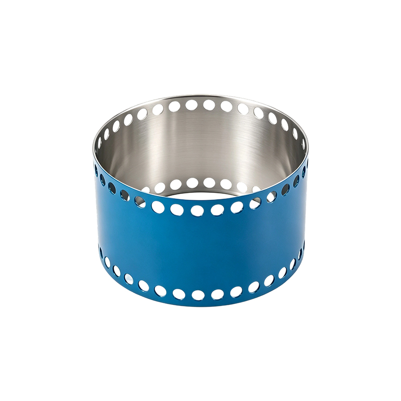
Inner Diameter 120 Steel Motor Housing
Product Overview
The Inner Diameter 120 Steel Motor Housing is a cylindrical steel enclosure intended to support and protect the stator, rotor, and related motor components. Its main function is to maintain the correct relationship between the internal motor assembly and the end covers while also providing mechanical protection and contributing to thermal performance.
The product has an internal diameter of 120 mm. This dimension is particularly important because it establishes the available space for the motor’s internal assembly and affects the fit between the stator core and the housing. An accurately controlled inner diameter helps reduce unwanted clearance, positioning variation, and assembly stress. It also gives motor designers a dependable dimensional basis when developing end covers, stator packs, bearing supports, and other associated components.
The housing height is 69.9 mm. This compact axial dimension enables the product to serve motor designs where installation space is limited or where a short overall motor package is preferred. The height must be controlled carefully because even a small deviation can influence end-cover positioning, rotor alignment, bearing preload, stator location, and the final axial length of the motor.
The wall thickness is only 1.2 mm. This thin-wall structure reduces material usage and overall housing weight while retaining the basic rigidity required for motor assembly and operation. Thin-wall steel components require disciplined forming and machining practices because dimensional distortion, edge deformation, ovality, or localized stress can have a larger effect than they would in a heavy-wall component. The design therefore emphasizes precision production rather than relying simply on excess material for strength.
The outer diameter is 122.4 mm. Together with the 120 mm inner diameter, this dimension corresponds to the stated 1.2 mm wall thickness. The close relationship between these dimensions is important for applications that require a defined external envelope for motor mounting, equipment integration, protective covers, brackets, or surrounding cooling structures.
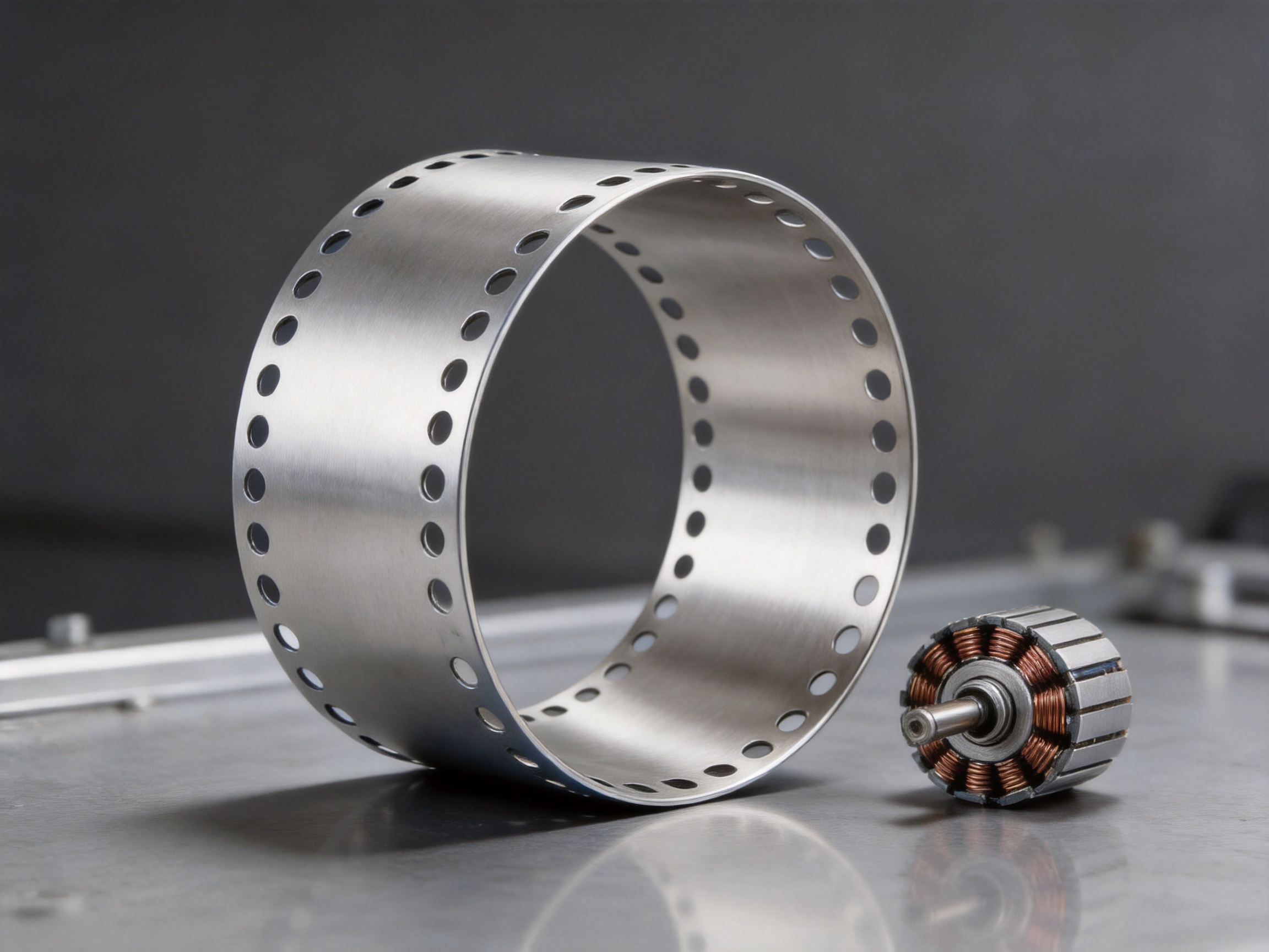
The housing also incorporates ventilation holes at both ends. These openings are intended to form an axial air-cooling channel through the interior of the housing. Air can move through the motor enclosure and assist in removing heat from the stator and rotor assemblies. In continuous-duty applications, improved airflow can help limit temperature rise and support more stable motor operation.
Key Technical Specifications
The following table summarizes the primary product data supplied for the Inner Diameter 120 Steel Motor Housing.
| Parameter | Specification | Engineering Significance |
|---|---|---|
| Product type | Steel motor housing | Provides structural protection and support for motor assemblies |
| Inner diameter | 120 mm | Defines the internal assembly space and stator interface |
| Height | 69.9 mm | Controls the axial housing envelope and end-cover relationship |
| Wall thickness | 1.2 mm | Supports lightweight construction and reduced material consumption |
| Outer diameter | 122.4 mm | Defines the external installation envelope |
| Materials specification | SPCC / ST12 / DC01 | Provides common low-carbon steel options for forming and fabrication |
| Roundness | ≤ 0.08 mm | Supports concentric assembly and stable internal alignment |
| End-face parallelism | Within 0.1 mm | Improves end-cover fit, assembly accuracy, and sealing reliability |
| Cooling design | Ventilation holes at both ends | Creates an axial airflow route through the housing |
Lightweight Design Without Sacrificing Practical Rigidity
One of the most important advantages of this product is its lightweight precision design. A 1.2 mm wall is considerably thinner than the wall used in many conventional heavy-duty housings. Reducing wall thickness can lower the mass of the motor assembly, decrease material consumption, and make handling easier during production and final equipment installation.
Lower weight is valuable in many types of equipment. In portable machinery, it can improve ease of movement and reduce the load on supporting structures. In household appliances, it can help manufacturers manage total product weight while preserving a robust motor enclosure. In industrial drive systems, reduced motor mass can simplify mounting and contribute to more efficient equipment packaging. In new energy vehicle systems and special equipment, every kilogram may affect system integration, energy consumption, or mechanical response.
However, lightweight construction must be balanced with dimensional stability. A thin housing that deforms during forming, machining, transportation, or assembly may create more problems than it solves. Excessive deformation can affect stator seating, rotor clearance, bearing alignment, noise, vibration, and the fit of the end covers. For this reason, the value of the 1.2 mm design does not come from thinness alone. Its advantage comes from combining thin-wall geometry with controlled manufacturing and inspection.
The stated roundness value of no more than 0.08 mm is especially relevant to this balance. Roundness control helps the cylindrical housing maintain a consistent internal shape rather than becoming significantly oval or irregular. This supports a more uniform interface with the stator and helps maintain a predictable position for internal components. It can also reduce localized contact or uneven stress during assembly.
Compared with generic low-cost housings that may prioritize material reduction without sufficient dimensional control, this product offers a more engineering-oriented approach. It is designed to reduce weight while retaining the precision needed for motor assembly. This combination can help customers avoid the hidden costs associated with excessive rework, difficult installation, inconsistent noise performance, or premature mechanical adjustment.
Precision of the Inner Diameter and Roundness
The inner diameter is one of the most influential dimensions in a motor housing. It determines how the stator and other internal components relate to the enclosure. If the diameter is too small, assembly may become difficult, and press-fit or insertion forces may increase. If the diameter is too large, the assembly may experience unwanted movement, poor heat transfer, or insufficient support. Variation around the circumference can create similar problems even when the average measured diameter appears correct.
The specified 120 mm inner diameter provides a clear dimensional reference for product development. Motor designers can use it when calculating the stator outside diameter, interference or clearance conditions, insulation allowances, and thermal expansion effects. It also provides a basis for selecting compatible end covers, bearings, and other components.
Roundness of no more than 0.08 mm helps control the difference between the housing’s ideal circular profile and its actual manufactured form. This matters because a motor’s rotating components require consistent alignment. A housing that is not sufficiently round may cause uneven clearances, localized loading, or difficulty maintaining the intended air gap between the stator and rotor.
Improved roundness can also contribute to more consistent heat transfer. A stable contact relationship between the stator and housing can support the movement of heat from the electromagnetic assembly toward the steel enclosure. Although total thermal performance depends on the complete motor design, housing geometry remains an important part of that system.
For manufacturers producing motors in volume, dimensional consistency is just as important as the nominal dimension itself. A housing that measures close to 120 mm in one batch but varies significantly in another can cause assembly adjustments and inconsistent finished-motor performance. A controlled roundness specification supports process stability and makes it easier for customers to establish repeatable assembly procedures.
End-Face Precision and Assembly Reliability
The end faces of a motor housing provide the connection surfaces for the end covers. These surfaces must be sufficiently accurate to ensure that the covers sit correctly and remain properly aligned after fastening or joining. The product is described as having precision-machined end faces with parallelism tolerance within 0.1 mm.
End-face parallelism affects more than appearance. If the two end faces are not properly related to one another, the end covers may not maintain the intended axial position. This can influence bearing alignment, rotor positioning, shaft runout, axial clearance, sealing pressure, and the mechanical behavior of the assembled motor.
A parallelism tolerance within 0.1 mm improves the probability of a consistent end-cover fit. It can reduce uneven gaps and minimize the risk that fasteners will pull one side of the cover into an unintended position. It also supports a more stable interface for sealing elements, which is important in applications where dust, moisture, lubricants, or process contaminants must be kept away from internal motor components.
Accurate end faces can also reduce assembly time. When housing and cover interfaces are produced consistently, operators and automated assembly equipment can complete the joining process with fewer adjustments. Reduced adjustment can increase line efficiency and lower the likelihood of assembly-related defects.
Compared with standard housings that receive limited finishing or inconsistent end-face treatment, the machined end surfaces of this product provide an important quality advantage. The benefit is particularly relevant to customers seeking predictable motor assembly, improved sealing reliability, and lower variation among finished units.
Axial Air Cooling Through End Ventilation
Thermal management is a central concern in electric motor design. During operation, electrical resistance, magnetic losses, bearing friction, and other sources generate heat. If that heat is not removed effectively, the motor temperature can rise beyond the preferred operating range. Excessive temperature can accelerate insulation aging, reduce lubricant life, affect dimensional stability, and shorten service life.
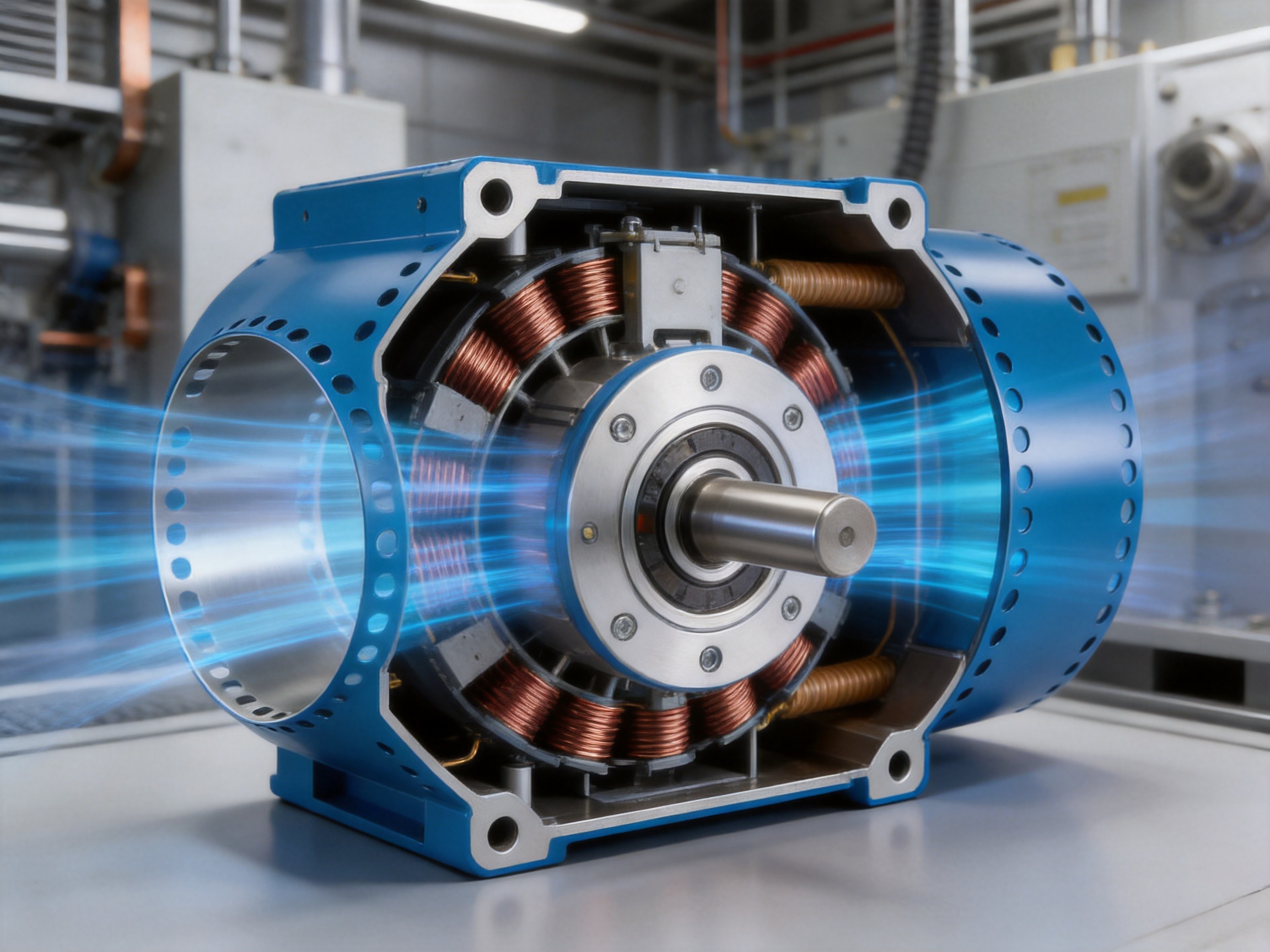
The Inner Diameter 120 Steel Motor Housing includes ventilation holes at both ends. These openings are designed to support an axial airflow route through the interior of the housing. As air passes through the enclosure, it can assist in carrying heat away from the stator and rotor assemblies.
The axial cooling concept is practical because it uses the length of the motor as a natural airflow direction. Instead of relying only on heat conduction through the housing wall, the design allows air movement to interact directly with internal heat sources. The effectiveness of the final cooling system will depend on the complete motor architecture, fan arrangement, airflow resistance, operating speed, ambient temperature, and ventilation path, but the housing provides a useful foundation for this strategy.
Ventilation can be particularly valuable in continuous-duty applications. Motors used for extended operating periods may experience a steady accumulation of heat. An efficient airflow channel can help reduce temperature rise and make the motor more capable of handling demanding work cycles. Lower operating temperature can also help preserve insulation systems and other temperature-sensitive components.
The ventilation arrangement may offer an advantage over fully enclosed designs when the application permits airflow through the motor. A fully sealed housing can provide protection against external contaminants, but it may require a larger heat-dissipation surface, additional cooling components, or a more complex thermal design. A ventilated housing offers an alternative for equipment where controlled airflow is acceptable and cooling efficiency is a priority.
Customers should evaluate the ventilation design together with their application environment. Where the motor operates in a dusty, wet, corrosive, or contaminated area, additional filtering, shielding, or enclosure protection may be required. The housing’s ventilation concept is therefore best understood as a thermal-management feature that must be integrated with the complete motor and equipment design.
Material Options: SPCC, ST12, and DC01
The listed materials specification includes SPCC, ST12, and DC01. These are commonly recognized low-carbon steel designations used in sheet and formed component manufacturing. Their suitability for a specific order should be confirmed according to the applicable material standard, thickness requirement, surface condition, forming method, and customer documentation.
Low-carbon steels are widely used for motor housings because they offer a practical balance of formability, strength, machinability, availability, and cost. They can be processed through stamping, forming, cutting, machining, welding, and surface-treatment operations. This makes them suitable for a housing that requires a formed cylindrical structure followed by dimensional finishing and inspection.
Material selection influences more than raw material price. It can affect forming behavior, springback, surface quality, weldability, machining response, corrosion protection, and dimensional stability after processing. By identifying recognized material options, the product provides a clear starting point for customers’ technical reviews and purchasing specifications.
Customers may select a material route according to their performance requirements and supply-chain preferences. For example, a project may prioritize forming behavior, another may require compatibility with a particular surface treatment, and a third may be governed by an established internal material standard. The manufacturer’s engineering team can support the review of material equivalence, process compatibility, and production feasibility.
Because the wall thickness is only 1.2 mm, material consistency is important. Variations in thickness, hardness, surface quality, or residual stress can influence the stability of forming and machining operations. Appropriate incoming inspection and process controls are therefore essential to achieve the intended geometry and appearance.
Manufacturing Process and Integrated Production Capability
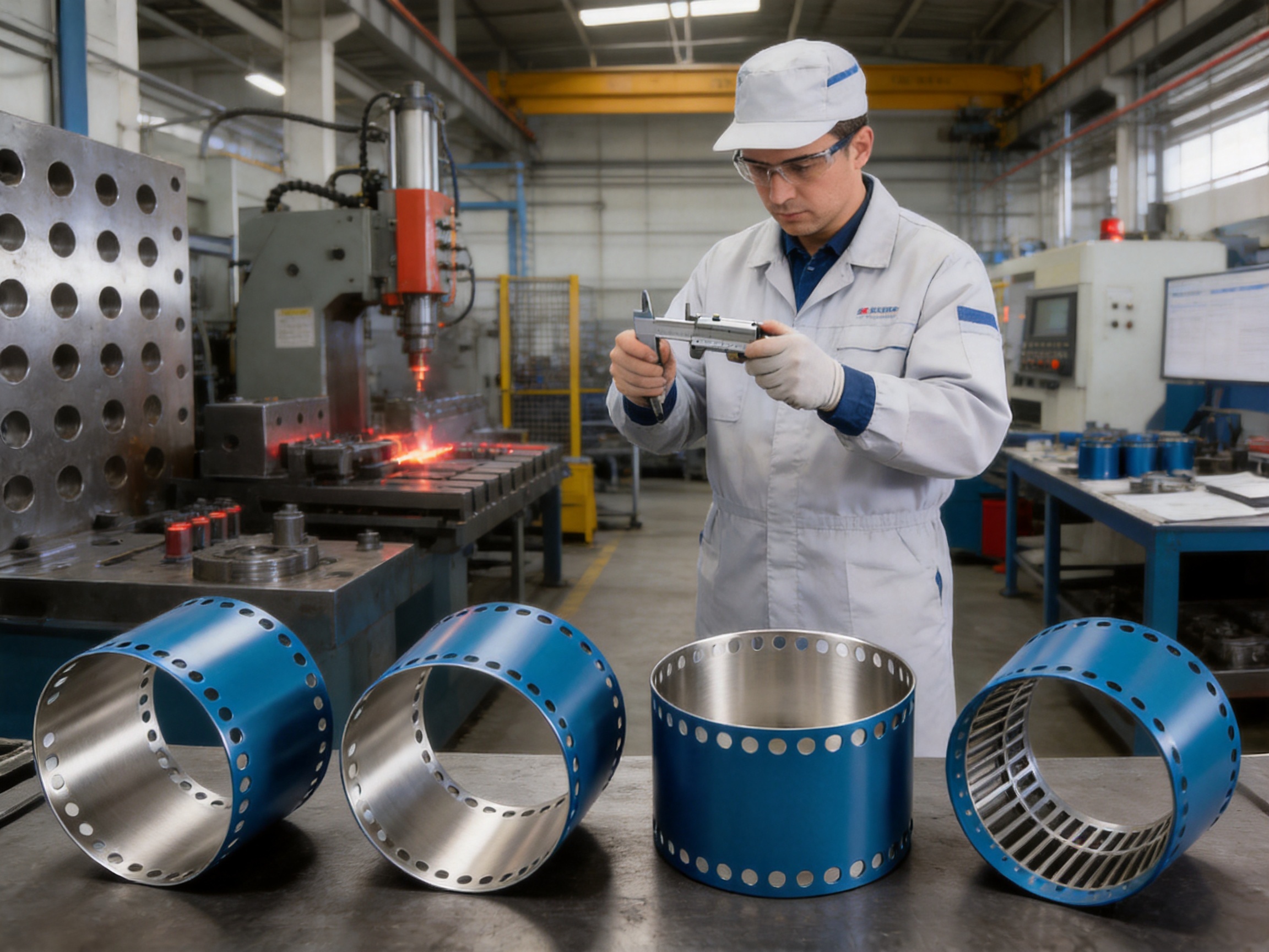
Jiangsu Yufeng Electric Co., Ltd. specializes in the research, development, and production of motor housings. Its manufacturing capabilities cover stamping, welding assembly, machining, surface treatment, and inspection. This full-process structure is an important strength for customers that require more than a simple raw formed shell.
The production process begins with engineering review and material preparation. At this stage, the manufacturer can examine the customer’s drawings, dimensional tolerances, application conditions, production volume, and required surface finish. The product’s 120 mm inner diameter, 69.9 mm height, 1.2 mm wall thickness, roundness specification, and end-face parallelism requirement all need to be translated into practical process controls.
Stamping and forming operations create the basic steel housing geometry. The forming process must be controlled to limit cracking, wrinkling, excessive springback, local thinning, and distortion. Tooling condition, press parameters, material properties, lubrication, and forming sequence can all affect the final cylindrical shape.
After forming, welding or joining operations may be used where required by the product structure or customer design. Automated welding equipment can help maintain repeatability and reduce variation caused by manual positioning. Proper welding control is especially important for thin-wall components because excessive heat input can produce distortion or affect the finished dimensional relationship.
Machining operations refine critical surfaces and dimensions. The end faces are precision-machined to achieve the stated parallelism tolerance within 0.1 mm. Additional machining may be applied to interfaces, mounting features, holes, edges, or other customer-specific details. The machining stage provides an opportunity to establish a more controlled relationship between the housing axis and the end-cover surfaces.
Surface treatment can be selected according to the customer’s environmental and appearance requirements. Steel motor housings may require protection against oxidation, handling damage, humidity, or operating exposure. The selected treatment should be evaluated for adhesion, thickness, durability, dimensional effect, and compatibility with assembly.
Inspection is integrated into the production approach. Inspection instruments are used to verify critical dimensions and product quality. For this housing, important inspection points may include inner diameter, outer diameter, height, wall thickness, roundness, ventilation-hole geometry, end-face condition, and parallelism. Depending on the customer’s quality plan, inspection can also include material verification, surface examination, weld evaluation, and packaging checks.
Why Integrated Manufacturing Matters to Customers
Using one manufacturer for multiple production stages can simplify communication. When stamping, machining, assembly, and finishing are divided among unrelated suppliers, responsibility for dimensional variation can become difficult to identify. A small deviation introduced during forming may be amplified during machining or assembly, and the customer may need to coordinate corrective action across several companies.
An integrated manufacturer can assess the complete process more directly. Engineering teams can evaluate whether a design is suitable for forming, determine where machining allowance is needed, and establish inspection points that reflect the final application. This can reduce the risk of designing a component that is theoretically correct but difficult or expensive to produce consistently.
Integrated production can also improve schedule control. Fewer external handoffs may reduce transportation time, intermediate storage, and coordination delays. It can make it easier to manage engineering changes, sample revisions, production approvals, and corrective actions. These benefits are especially relevant when customers are moving from prototype quantities to mass production.
Another advantage is traceability. When more process data is generated and retained within one production organization, it can be easier to connect raw material information, forming records, machining results, inspection reports, and shipment documentation. Traceability requirements vary by customer and application, but centralized control provides a stronger foundation for quality management.
Advantages Over Generic and Heavy-Wall Alternatives
The product has several advantages when compared with generic steel housings that use a heavier wall or provide less controlled dimensional finishing.
First, the 1.2 mm wall thickness can reduce weight and material usage. A heavy-wall housing may offer additional mass, but that mass is not always necessary for the application. If the motor’s mechanical and thermal requirements can be met with a controlled thin-wall design, the lighter solution may support easier handling and more compact equipment integration.
Second, the specified roundness of no more than 0.08 mm offers a measurable geometric target. Generic housings may be produced with broad or poorly defined shape tolerances, creating uncertainty during stator insertion and motor assembly. A controlled roundness value gives customers a clearer basis for quality acceptance and process validation.
Third, the end-face parallelism within 0.1 mm supports better cover alignment and sealing reliability. A housing with untreated or inconsistently finished ends may require more assembly adjustment. Precision-machined end faces can reduce this risk and support repeatable end-cover installation.
Fourth, the ventilation holes at both ends create an intentional axial airflow route. A basic enclosed cylinder may provide mechanical protection but offer less direct support for internal airflow. For applications where ventilation is permitted, the product’s cooling-oriented design can contribute to more effective heat removal.
Fifth, the product is supported by a manufacturer with multiple in-house process capabilities. Customers do not receive only a formed steel tube; they can access a broader manufacturing resource capable of supporting development, machining, assembly, surface treatment, and inspection.
These advantages should not be interpreted as a guarantee that the housing will outperform every alternative in every application. Final performance depends on the motor design, operating conditions, assembly method, cooling system, surface protection, and quality requirements. Nevertheless, the combination of lightweight construction, dimensional control, precision end faces, ventilation, and integrated manufacturing provides a strong value proposition for many motor applications.
Applications Across Multiple Industries
The housing is suitable for consideration in household appliances, industrial drives, new energy vehicles, and special equipment. Each application category has different requirements, but all can benefit from a housing that combines compact geometry and controlled production.
Household Appliances
Household appliances often place strong emphasis on low noise, compact size, weight control, thermal stability, and cost-effective mass production. A precisely formed housing can support consistent motor assembly and help manufacturers manage product variation across large production volumes.
The ventilation concept may be useful in appliance motors where airflow can be controlled within the equipment. The lightweight structure can also support easier product handling and contribute to overall appliance weight reduction. Depending on the appliance environment, surface treatment and protection against humidity or condensation should be selected appropriately.
Industrial Drives
Industrial drive systems may operate for long periods and under demanding load conditions. In these applications, thermal behavior and mechanical consistency are particularly important. The axial ventilation design can support airflow through the motor, while the controlled inner diameter and end-face parallelism can assist with accurate assembly.
Industrial customers may also value the manufacturer’s ability to support customized machining, welding, inspection, and surface-treatment requirements. The standard 120 mm housing geometry can serve as a starting point for adaptation to a specific drive system.
New Energy Vehicles
New energy vehicle systems require careful management of weight, packaging space, heat, vibration, and production consistency. The thin-wall steel structure may help support compact motor integration where a robust but relatively light enclosure is desired.
Vehicle applications usually involve demanding validation requirements, including environmental exposure, vibration, thermal cycling, corrosion resistance, and high-volume production capability. The housing should therefore be evaluated as part of the complete vehicle motor system, with the required surface treatment, joining method, inspection plan, and validation program defined before production approval.
Special Equipment
Special equipment frequently requires customized dimensions, mounting arrangements, ventilation patterns, or surface finishes. A manufacturer with engineering and multi-process capabilities can help adapt the basic housing concept to a specialized operating environment.
Applications may include dedicated machinery, equipment modules, compact automation systems, and other motor-driven assemblies. In these cases, the ability to review a drawing, produce samples, refine tooling, and transition to volume production can be as important as the nominal housing dimensions.
Engineering Considerations Before Ordering
Customers should confirm the complete technical requirement before placing an order. The nominal product data provides an important starting point, but the final housing must match the motor’s mechanical, electrical, thermal, environmental, and assembly conditions.
The first consideration is the internal interface. Customers should verify the stator outside diameter, intended fit condition, insulation system, thermal expansion allowance, and assembly method. If the stator is inserted, pressed, bonded, or otherwise secured, the housing tolerance and surface condition should be reviewed together with the stator specification.
The second consideration is the end-cover interface. The customer should provide end-cover dimensions, bolt-hole locations, sealing requirements, bearing-seat relationships, and axial stack-up information. The stated end-face parallelism is valuable, but other interfaces may require additional machining or inspection controls.
The third consideration is ventilation. The location, number, and size of the ventilation holes should be checked against the customer’s airflow requirements and contamination environment. If the motor will operate near dust, water, oil mist, or corrosive substances, protective measures may be necessary.
The fourth consideration is corrosion protection. The customer should specify whether the housing will receive painting, plating, coating, oil protection, or another surface treatment. The treatment must be compatible with the operating environment and should not interfere with the dimensional interfaces or electrical grounding requirements.
The fifth consideration is quality documentation. Customers may require material certificates, dimensional inspection reports, process control plans, first-article inspection data, sample approval records, or batch traceability. These requirements should be discussed early so that the production and inspection systems can be prepared accordingly.
The sixth consideration is production volume. Prototype, small-batch, and mass-production requirements may involve different tooling strategies, inspection frequencies, packaging methods, and cost structures. Early communication allows the manufacturer to recommend a practical route from initial samples to stable production.
Quality Control and Process Consistency
Quality control for a thin-wall motor housing should cover the entire process rather than relying only on final inspection. Incoming steel quality, forming behavior, joining stability, machining accuracy, surface treatment, and packaging can all affect the final product.
Incoming inspection can verify material specification, thickness, surface condition, and basic flatness or hardness information where required. Process inspection during forming can monitor the cylindrical profile, height, edge condition, and potential deformation. Machining inspection can focus on end-face parallelism, interface dimensions, and hole locations.
Final inspection should verify the dimensions and characteristics that are most important to the motor assembly. These include the 120 mm inner diameter, 122.4 mm outer diameter, 69.9 mm height, 1.2 mm wall thickness, roundness of no more than 0.08 mm, and end-face parallelism within 0.1 mm. The exact measurement method and sampling frequency should be agreed with the customer.
Inspection equipment must be suitable for thin-wall cylindrical components. Conventional tools may not provide enough accuracy or repeatability for every feature. Depending on the production requirement, manufacturers may use precision gauges, coordinate measurement equipment, roundness measurement systems, optical instruments, or dedicated inspection fixtures.
Packaging is also part of quality preservation. A dimensionally accurate housing can be damaged if it is allowed to collide with other components during transport. Protective separators, suitable stacking, moisture control, and clear batch identification can help preserve the product condition from the factory to the customer’s assembly line.
Manufacturer Experience and Engineering Support
Jiangsu Yufeng Electric Co., Ltd. reports 40 years of experience in motor housing manufacturing and an annual production capacity of more than 5 million units. The company has served more than 50 customers and supports products used in household appliances, industrial drives, new energy vehicles, and special equipment.
Long-term experience can be valuable because motor housing production involves many practical variables that are not always fully represented in a drawing. Tool wear, material springback, welding distortion, machining allowance, coating thickness, packaging pressure, and assembly behavior can all influence the final result. An experienced engineering team is better positioned to identify these issues during product development.
The company also states that its engineering team has an average of more than 20 years of experience. This supports technical cooperation from initial product development through mass production. Customers may benefit from design-for-manufacturing feedback, prototype evaluation, process optimization, and production troubleshooting.
The manufacturer’s full in-house production model includes stamping, welding assembly, machining, and surface treatment. This combination provides a single point of technical coordination for customers seeking a complete housing solution. It also supports faster response when a design modification affects multiple operations.
For overseas and domestic customers, responsive communication is important. Clear exchange of drawings, specifications, sample requirements, inspection criteria, packaging instructions, and delivery schedules can reduce misunderstandings. The manufacturer’s stated focus on quality, efficiency, and fast response aligns with the practical needs of customers developing or scaling motor products.
Customization Potential
The standard product has a 120 mm inner diameter, but many motor projects require adaptation. Possible customization areas may include housing height, wall thickness, ventilation-hole pattern, mounting holes, end-face features, welding details, surface treatment, and packaging configuration.
Customization should begin with a complete technical review. The customer should provide two-dimensional drawings, three-dimensional models when available, applicable standards, material requirements, expected annual volume, and application information. The manufacturer can then evaluate tooling, forming feasibility, machining requirements, inspection methods, and estimated production lead time.
Ventilation customization may be important when the motor must meet a specific airflow or acoustic target. Hole geometry and location can affect airflow resistance, structural stiffness, debris entry, and manufacturing complexity. Any change should therefore be validated with the complete motor design rather than considered as an isolated feature.
Surface treatment customization may also be required. A motor used indoors in a clean environment may need a different finish from one used outdoors or near industrial chemicals. The selected treatment should be tested for corrosion resistance, coating adhesion, dimensional impact, and compatibility with assembly.
Prototype samples are useful for verifying fit, assembly sequence, airflow, noise, vibration, and thermal behavior. After sample approval, process documentation and inspection criteria can be finalized for volume production. This staged approach helps reduce risk before large quantities are manufactured.
Installation and Assembly Recommendations
Before assembly, the housing should be checked for dents, burrs, contamination, coating defects, and damage to the end faces. Even a small dent in a thin-wall housing can influence roundness or interfere with the stator installation. Clean handling practices are therefore important.
The stator and other internal components should be inserted using the approved assembly method. Excessive force or uneven loading can deform the housing, particularly when the wall thickness is only 1.2 mm. Dedicated fixtures or controlled insertion equipment may be appropriate for high-volume production.
End covers should be installed in a sequence that maintains alignment and distributes fastening force evenly. Fastener torque should follow the customer’s approved specification. Uneven tightening may affect end-face contact, sealing pressure, bearing alignment, or housing geometry.
Ventilation holes should remain unobstructed after assembly. Gaskets, wiring, brackets, adhesive, or protective materials must not unintentionally block the designed airflow channel. If the final motor includes a fan or forced-air system, airflow direction and resistance should be confirmed during testing.
After assembly, customers should evaluate noise, vibration, shaft rotation, temperature rise, leakage or sealing performance where applicable, and overall dimensional conformity. These checks help confirm that the housing performs correctly as part of the complete motor rather than only as an individual component.
Maintenance and Service Life Considerations
A motor housing does not operate independently from the motor’s maintenance program. The ventilation path should be inspected periodically in applications where dust or debris may accumulate. Blocked openings can reduce airflow and lead to higher operating temperatures.
Surface condition should also be monitored in humid, corrosive, or outdoor environments. Any damage to the protective finish should be assessed and repaired according to the applicable maintenance procedure. Corrosion can reduce the effective wall thickness and may eventually affect structural or sealing performance.
Fasteners and end-cover joints should be checked when the equipment experiences significant vibration or repeated thermal cycling. The inspection interval depends on the application, but early detection of loosened joints or damaged seals can help prevent secondary motor damage.
Operating temperature should be evaluated during commissioning and routine service. The housing’s axial ventilation design can support cooling, but the final thermal result depends on airflow, load, speed, ambient conditions, and motor construction. Monitoring these factors helps ensure that the housing and motor remain within their intended operating range.
Frequently Asked Questions
What is the inner diameter of this steel motor housing?
The inner diameter is 120 mm. This dimension defines the primary internal space for the stator and related motor components.
What are the housing height and outer diameter?
The stated height is 69.9 mm, and the outer diameter is 122.4 mm.
What is the wall thickness?
The wall thickness is 1.2 mm. This supports a lightweight construction while requiring careful forming, machining, handling, and inspection.
What materials can be used?
The listed materials specification is SPCC, ST12, or DC01. The final material should be confirmed according to the customer’s drawing, applicable standards, surface requirements, and production conditions.
How accurate is the roundness?
The stated roundness specification is no more than 0.08 mm. This supports a more consistent circular profile for stator installation and internal alignment.
What is the end-face parallelism tolerance?
The precision-machined end faces have a parallelism tolerance within 0.1 mm. This is intended to improve end-cover fit, assembly accuracy, and sealing reliability.
How does the housing support cooling?
Ventilation holes are designed at both ends of the housing to establish an axial airflow channel. Air can pass through the interior and assist in cooling the stator and rotor assemblies. Final cooling performance depends on the complete motor design and operating conditions.
Is this housing suitable for continuous-duty motors?
It can be considered for continuous-duty applications where the motor design permits axial ventilation and the complete thermal system is properly engineered. Customers should validate temperature rise under the intended load, speed, ambient temperature, and airflow conditions.
Can the housing be customized?
Customization may be possible for dimensions, ventilation holes, machining features, joining details, surface treatment, and packaging. A technical review based on drawings and application requirements is recommended before development.
What manufacturing processes are available?
The manufacturer provides integrated capabilities including stamping, welding assembly, machining, surface treatment, and inspection. These capabilities support production from formed steel components to finished motor housing solutions.
What industries can use this product?
The housing is suitable for consideration in household appliances, industrial drives, new energy vehicles, and special equipment. The final suitability depends on the required mechanical, thermal, environmental, and assembly specifications.
How should customers begin a project?
Customers should provide the housing drawing or model, material requirements, annual demand, end-cover interface information, ventilation requirements, surface-treatment expectations, inspection standards, and application environment. This information enables a more accurate feasibility and quotation review.
Conclusion
The Inner Diameter 120 Steel Motor Housing combines a compact 120 mm internal diameter with a 69.9 mm height, 122.4 mm outer diameter, and lightweight 1.2 mm wall. Its design is focused on practical motor requirements: controlled roundness, accurate end faces, reliable end-cover fit, reduced weight, and improved airflow through axial ventilation.
The product’s stated roundness of no more than 0.08 mm and end-face parallelism within 0.1 mm provide clear dimensional targets for assembly quality. These features can help support concentric internal alignment, stable end-cover positioning, improved sealing, and consistent motor production. The ventilation holes at both ends create a cooling-oriented structure that may help reduce temperature rise when integrated with an appropriate motor airflow system.
Compared with generic or heavy-wall alternatives, the housing offers a combination of lightweight construction, precision geometry, and production flexibility. Its value is strengthened by Jiangsu Yufeng Electric Co., Ltd.’s integrated capabilities in stamping, welding assembly, machining, surface treatment, and inspection, together with decades of motor housing manufacturing experience and an annual production capacity exceeding 5 million units.
For customers developing a new motor or improving an existing design, this housing provides a strong starting point for a compact, manufacturable, and thermally conscious solution. Final performance should always be verified within the complete motor assembly, but the product’s dimensional control, material options, ventilation concept, and integrated manufacturing support make it a practical choice for demanding electric motor applications.
References
1. Product specification data for the Inner Diameter 120 Steel Motor Housing, including dimensions, material options, roundness, and ventilation features.
2. General engineering principles for electric motor housing design, dimensional control, end-cover alignment, and thermal management.
3. General material references for SPCC, ST12, and DC01 low-carbon steel grades used in formed and machined components.
4. General manufacturing practices for steel stamping, thin-wall forming, welding assembly, precision machining, surface treatment, and dimensional inspection.
5. General quality-control principles for cylindrical motor housings, including roundness verification, end-face parallelism, traceability, and final assembly inspection.

 Previous