

 English
 Español
Content
- 1 Product Overview and Structural Configuration
- 2 Advantages of Heavy-Wall Construction
- 3 Mechanical Protection for High-Power Motor Operation
- 4 Integrated Terminal Block for Electrical Convenience
- 5 Top Lifting Lug for Handling and Installation
- 6 Bottom Mounting Foot for Stable Support
- 7 Manufacturing Capabilities Supporting Product Quality
- 8 Inspection and Process Control
- 9 Why the Product Offers an Advantage Over Conventional Alternatives
- 10 Application Areas
- 11 Design and Selection Considerations
- 12 Production from Development to Mass Delivery
- 13 Company Strengths in Motor Housing Manufacturing
- 14 Installation, Handling, and Maintenance Guidance
- 15 Value for Equipment Manufacturers and System Integrators
- 16 Frequently Asked Questions
- 16.1 What are the main dimensions of the motor housing?
- 16.2 What type of material is used?
- 16.3 Why is a 5 mm wall thickness beneficial?
- 16.4 Does the housing include a terminal block?
- 16.5 What is the purpose of the top lifting lug?
- 16.6 What is the purpose of the bottom mounting foot?
- 16.7 Which applications are suitable for this product?
- 16.8 Can the housing be customized?
- 16.9 What manufacturing processes are available from the supplier?
- 16.10 How should customers confirm compatibility before ordering?
- 17 Conclusion
- 18 References
- 19 Product: Inner Diameter 260 Heavy-Wall Motor Housing With Base
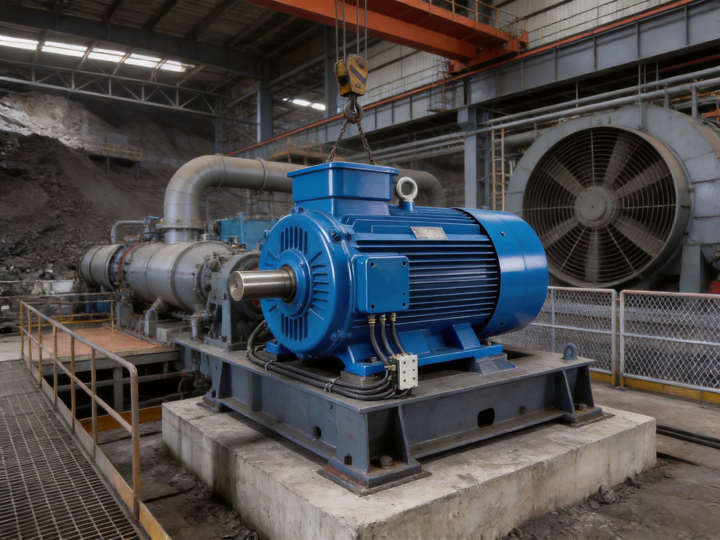
High-power electric motors operate under demanding mechanical, thermal, and electrical conditions. During continuous operation, the motor enclosure must protect internal components from vibration, impact, dust, accidental contact, and installation-related stress. At the same time, it must maintain dimensional stability, provide reliable mounting, support practical cable connection, and remain suitable for transportation and field maintenance. A motor housing that performs only as a thin protective shell may be insufficient for heavy industrial service. Large motors require a stronger structural solution capable of supporting torque, vibration, impact, and the weight of the complete motor assembly.
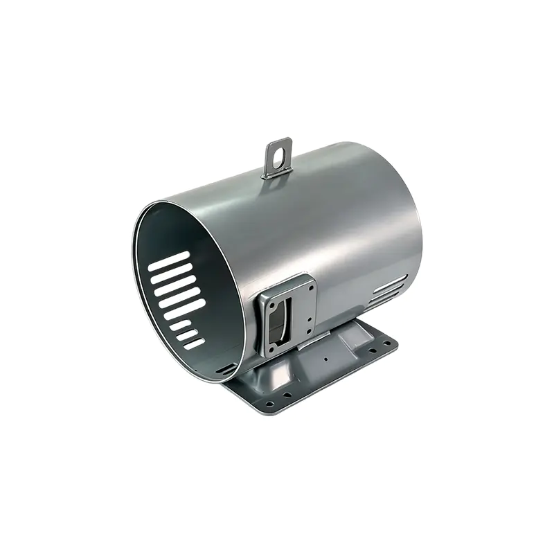
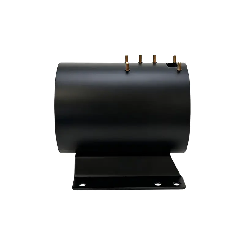
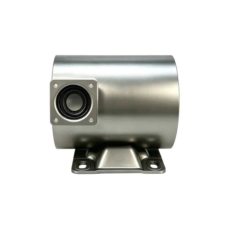
The Inner Diameter 260 Heavy-Wall Motor Housing With Base is designed for these demanding requirements. It features an inner diameter of 260 millimeters, a height of 360 millimeters, and a material thickness of 5 millimeters. This heavy-wall construction provides a substantial increase in rigidity compared with conventional light-gauge motor shells. The housing is further equipped with a welded terminal block, a top lifting lug, and a bottom mounting foot. These integrated features transform the component from a simple cylindrical enclosure into a practical structural module for motor assembly, installation, operation, and maintenance.
Manufactured by Jiangsu Yufeng Electric Co., Ltd., the housing benefits from an integrated production system covering steel processing, stamping, welding, machining, assembly, and surface treatment. This full-process capability allows the manufacturer to manage important quality factors internally, including dimensional consistency, weld reliability, component alignment, surface condition, and production efficiency. The result is a motor housing solution intended for large industrial motors, mining crusher motors, compressor motors, heavy-duty fan motors, and other equipment exposed to demanding operating conditions.
Product Overview and Structural Configuration
The primary body of the product is a cylindrical heavy-wall steel motor housing. The 260 mm inner diameter establishes the available internal space for the motor stator and related components, while the 360 mm height defines the axial enclosure dimension. A 5 mm wall thickness gives the shell a solid and durable structure. These dimensions make the housing suitable for applications where a stronger enclosure is needed than a standard thin-wall design can provide.
The housing is not supplied as an isolated tube without practical installation features. A terminal block is welded onto the body, a lifting lug is welded at the top, and a mounting foot is welded at the bottom. Each feature serves a different purpose. The terminal block supports organized electrical connections. The lifting lug supports handling and installation. The mounting foot provides a stable support point for positioning and fixation. Integrating these features into the housing reduces the need for separate brackets and can simplify the overall motor assembly.
The configuration is especially valuable for equipment designers who want to combine enclosure protection, structural support, and installation convenience in one manufactured component. Instead of designing a cylindrical shell first and adding multiple auxiliary parts later, the housing can be incorporated into a more coordinated motor architecture. This approach can help reduce assembly complexity and may improve the consistency of the final product when dimensions and welded features are controlled through a defined manufacturing process.
| Item | Specification or Feature | Functional Benefit |
|---|---|---|
| Product type | Heavy-wall steel motor housing | Provides a rigid protective enclosure for internal motor components |
| Inner diameter | 260 mm | Defines the internal motor accommodation space |
| Height | 360 mm | Supports the required axial enclosure dimension |
| Material thickness | 5 mm | Improves compression, impact, and deformation resistance |
| Terminal block | Welded to the housing | Facilitates organized motor power-wire connection and maintenance |
| Lifting lug | Welded on the top | Supports hoisting, handling, and installation operations |
| Mounting foot | Welded on the bottom | Provides stable single-point support and positioning |
| Primary material | Steel | Offers structural strength and suitability for industrial equipment |
Although the housing has a defined standard configuration, the manufacturing approach is also compatible with project-based engineering. Motor housings often need to match a specific stator, bearing arrangement, base structure, terminal position, cable routing requirement, or equipment installation method. A manufacturer with stamping, welding, machining, assembly, and finishing capabilities can evaluate these requirements across multiple production stages rather than treating the housing as a one-operation product.
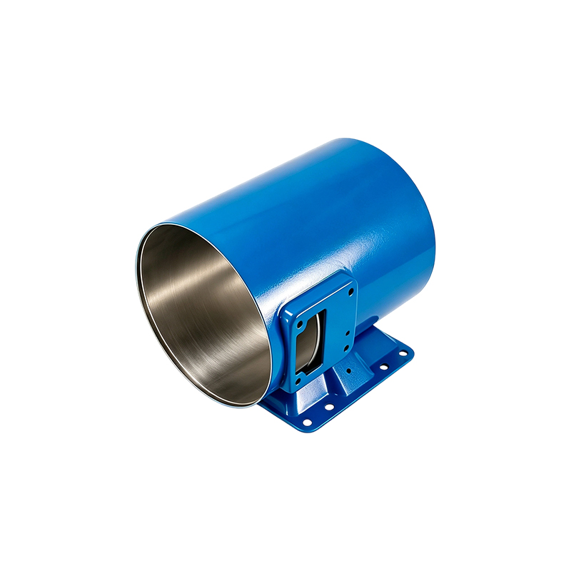
Inner Diameter 260 Heavy-Wall Motor Housing With Base
Advantages of Heavy-Wall Construction
The most important feature of this motor housing is its 5 mm steel wall. Heavy-wall construction increases the amount of material supporting the cylindrical structure and helps the body resist forces that may cause bending, denting, ovalization, or local deformation. In a high-power motor, these forces can be generated by electromagnetic torque, rotating imbalance, start-stop cycles, mechanical shock, coupling loads, and vibration transmitted from adjacent equipment.
A thin enclosure may be adequate for a low-load application with limited external stress, but heavy industrial equipment presents a different environment. Mining machinery, compressors, fans, and large drive systems may operate for long periods under fluctuating loads. They may also experience impact during installation, transportation, or maintenance. A thicker steel wall provides a stronger physical barrier and offers greater tolerance against handling damage and operating stress.
Compression resistance is another important benefit. The housing may be exposed to clamping forces, support reactions, local bracket loads, or pressure caused by adjacent components. A heavy-wall shell is less likely to collapse or buckle under these conditions than a lighter shell of the same general diameter. This resistance contributes to the protection of the stator and other internal parts by helping preserve the intended internal geometry.
Impact resistance is particularly valuable in industrial environments. Equipment may be moved using cranes, forklifts, lifting tools, or temporary supports. Accidental contact with surrounding structures can damage a thin housing and create alignment problems. The 5 mm wall does not eliminate the need for careful handling, but it provides a stronger defense against common mechanical impacts and helps the enclosure maintain its protective function.
Deformation resistance also supports long-term reliability. If the cylindrical body becomes distorted, the internal clearances between rotating and stationary components may change. Even a relatively small change in geometry can affect assembly accuracy, rotor alignment, vibration behavior, and maintenance access. A rigid housing helps preserve the relationship between internal components and external mounting features, supporting a more stable motor structure throughout its service life.
The heavy-wall design may also offer advantages during fabrication. A thicker steel section can provide a more substantial foundation for welded accessories such as the terminal block, lifting lug, and mounting foot. When these components are properly positioned and welded, the resulting assembly can better distribute local loads into the main shell. This is important because lifting and mounting forces are not applied uniformly across the entire enclosure; they are concentrated at specific attachment points.
Mechanical Protection for High-Power Motor Operation
Large motors generate high torque during starting, acceleration, and load changes. Torque is transferred through the rotor and motor frame, creating reaction forces that must be managed by the complete motor structure. The housing is part of that structure. Its function is not simply to cover the stator; it must maintain sufficient stiffness to support the motor assembly and limit unwanted movement.
Vibration is another critical consideration. Sources of vibration can include rotor imbalance, bearing conditions, misalignment, electromagnetic forces, foundation movement, and connected equipment. A rigid housing can help reduce structural flexing and can provide a more stable platform for mounting and alignment. While the housing alone cannot correct poor balancing or faulty installation, its strength supports the overall mechanical system and helps prevent enclosure-related vibration problems.
Impact loads may occur during operation or handling. Mining crushers, for example, can transmit intermittent shock through the drive train and foundation. Compressor systems may experience pulsating loads and repeated start-stop cycles. Heavy-duty fans may operate continuously while exposed to dust, temperature changes, and mechanical vibration. These applications benefit from a motor housing designed with greater structural reserve than a lightweight enclosure.
The 360 mm housing height also contributes to the overall enclosure architecture. Height must be considered together with internal clearances, stator placement, end-shield arrangements, bearing support, and terminal access. A properly manufactured body with controlled height and diameter helps the motor builder maintain the intended assembly relationship. For production users, dimensional consistency is important because even small variations can create fitting problems when housings are installed into larger machines.
In addition to mechanical strength, steel provides a practical basis for industrial motor housing production. Steel can be formed, welded, machined, inspected, and finished using established manufacturing methods. Its availability and process compatibility make it suitable for repeat production as well as customized project requirements. The material can be selected and processed according to the required balance between strength, fabrication efficiency, weight, and surface protection.
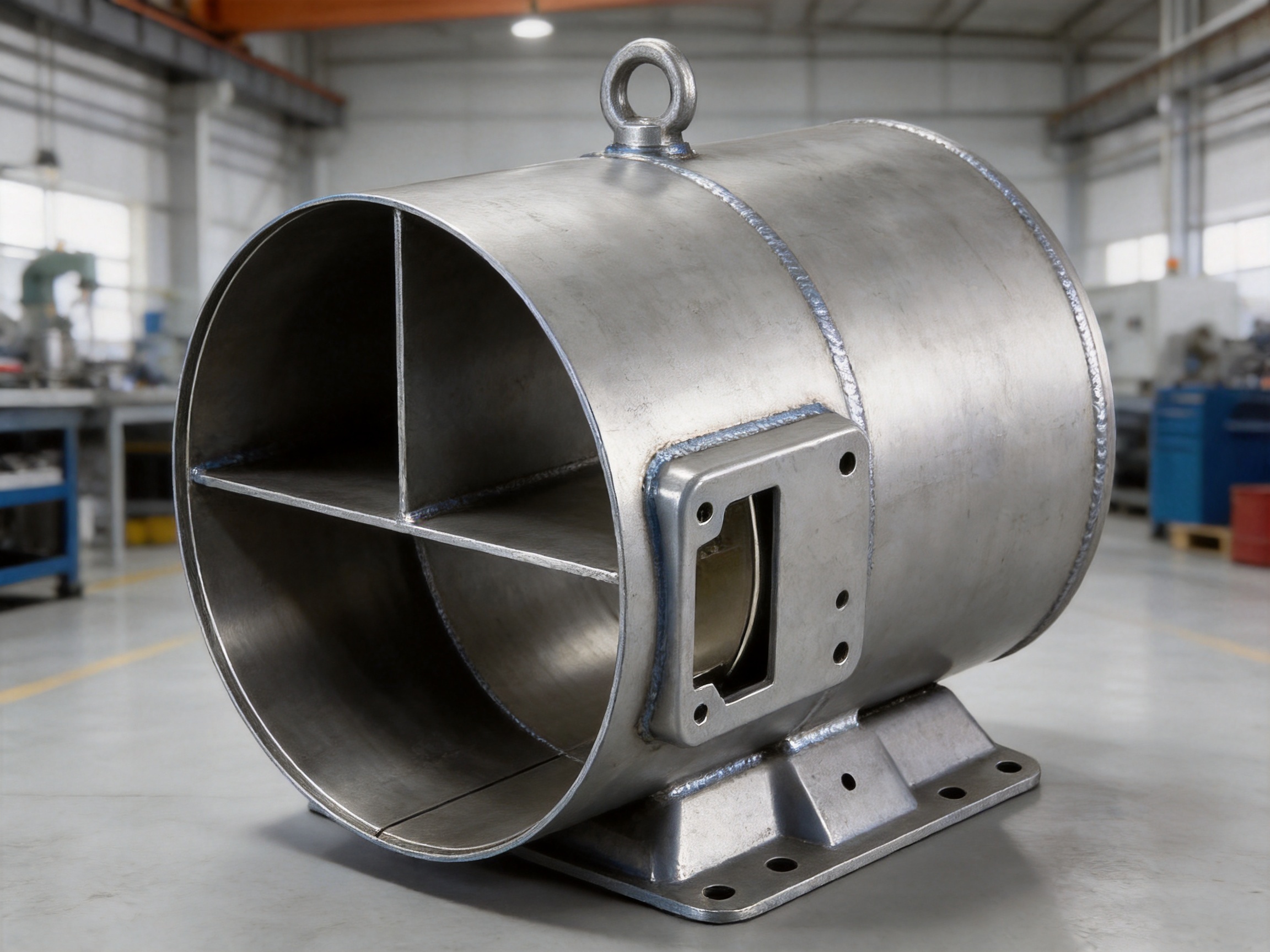
Integrated Terminal Block for Electrical Convenience
The welded terminal block is a significant functional addition to the housing. Motor power wires must be connected safely, consistently, and accessibly. An external or poorly supported terminal arrangement can create unnecessary installation work and may expose the cable connection to mechanical damage. By integrating a terminal block with the housing, the design provides a defined location for connection and fixing of the motor power wires.
High-standard welding is essential for this feature. The terminal block must remain firmly attached during cable installation, operation, vibration, and maintenance. A secure welded connection reduces the risk of movement, loosening, or misalignment. It also allows the terminal area to be treated as part of the housing assembly rather than as a temporary accessory attached after production.
Standardized connection improves maintenance convenience. Technicians can identify the intended connection point more easily, organize cables more effectively, and access the terminal area without searching for an improvised bracket or support. A well-positioned terminal block may also make it easier to route wires away from moving parts, hot surfaces, sharp edges, and areas exposed to excessive vibration.
The terminal block can be valuable for original equipment manufacturers and system integrators. When the connection location is consistent from one housing to another, assembly procedures can be standardized. Cable lengths, fasteners, protective covers, and inspection steps can be planned in advance. This can reduce variation during production and help maintenance teams follow a repeatable service procedure.
Electrical safety remains dependent on the complete motor system, including insulation, terminals, cable selection, grounding, protection devices, and installation practice. The welded terminal block supports a safer and more organized connection arrangement, but it should be used in accordance with the applicable electrical design and safety requirements for the finished motor.
Top Lifting Lug for Handling and Installation
A heavy motor housing can be difficult to position manually. The lifting lug welded to the top provides a designated point for hoisting, handling, and on-site installation. This is especially useful when the housing is incorporated into a large motor or when the motor must be moved into a confined equipment area.
A dedicated lifting point offers several advantages over improvised lifting methods. Operators do not need to wrap lifting equipment around sensitive components or attach tools to unsuitable brackets. A defined lug helps guide the handling procedure and can reduce the likelihood of damage to the housing, terminal block, cables, or other motor parts. It also improves the repeatability of installation work, particularly in industrial plants where large motors may need to be removed and reinstalled during maintenance.
The lifting lug must be evaluated as part of the complete lifting system. The actual safe working load depends on the lug design, weld quality, lifting angle, attachment method, housing condition, and total weight of the motor assembly. The lug should not be assumed to support a load greater than its engineering and inspection specifications. Proper lifting equipment and approved handling procedures remain essential.
From a production standpoint, welding the lug onto the housing allows the manufacturer to control its position, orientation, and attachment quality. Consistent positioning helps ensure that the motor can be lifted in a predictable manner. It also allows the lifting feature to be coordinated with the center of gravity, terminal position, and other structural components during the design stage.
For maintenance teams, the lug can shorten preparation time. Instead of creating a temporary support arrangement for each service event, workers can use the designated feature with appropriate tools. This contributes to improved operational convenience and can help reduce handling risks during assembly and repair.
Bottom Mounting Foot for Stable Support
The bottom mounting foot provides stable single-point support for positioning and fixation. In compact machinery, the available installation space may not permit a large base frame or multiple external brackets. An integrated mounting foot can simplify the structural design by combining housing support and motor positioning in one configuration.
A stable support point helps keep the motor correctly located during assembly. It can assist with alignment to connected equipment, reduce movement caused by vibration, and provide a clear reference for installation. The foot can also make it easier to design a mounting interface between the motor housing and the machine frame.
Because the mounting foot is welded to the heavy-wall body, its loads are transferred into a substantial steel structure. This can provide a stronger foundation than a light accessory bracket attached to a thin shell. The final support performance still depends on weld design, fastener selection, foundation rigidity, alignment, and the operating load of the motor.
The integrated foot may be particularly useful in restricted spaces. A motor designer can plan cable access, lifting access, and base fixation around the defined housing geometry. This can reduce the number of separate components required for installation and may help simplify the overall unit structure. For equipment manufacturers, fewer loose brackets can also reduce inventory requirements and assembly steps.
When installing the motor, the mounting surface should be checked for flatness, cleanliness, and sufficient strength. Fasteners should be tightened according to the approved engineering requirements, and alignment should be verified before operation. The mounting foot is designed to facilitate stable fixation, but it must be incorporated into a complete installation system that accounts for vibration, torque reaction, and foundation conditions.
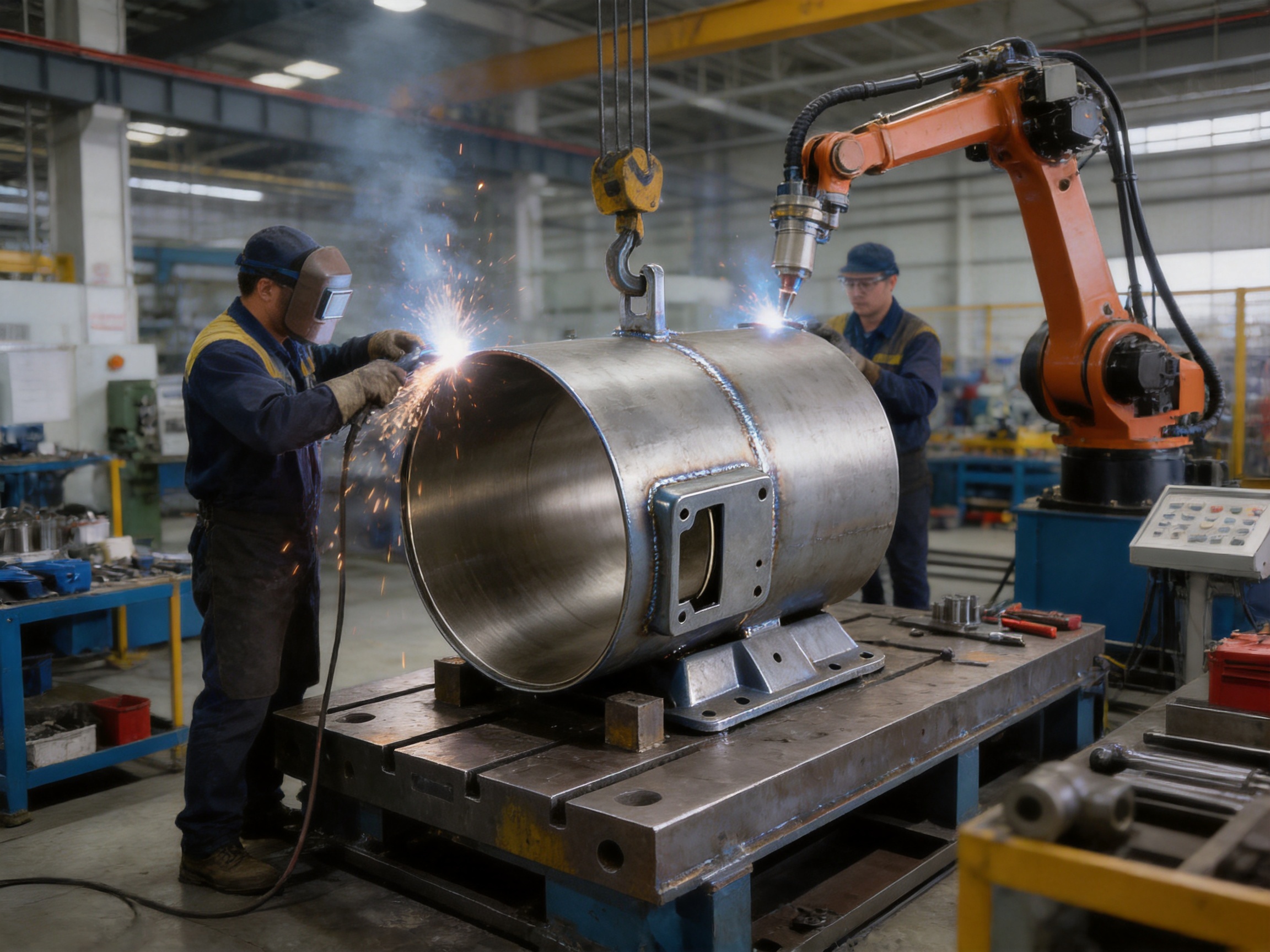
Manufacturing Capabilities Supporting Product Quality
Jiangsu Yufeng Electric Co., Ltd. operates as a professional manufacturer specializing in motor housings and related production processes. Its manufacturing scope includes stamping, welding assembly, machining, and surface treatment. This integrated capability is important because motor housing quality is determined by the interaction of many stages rather than by the cylindrical body alone.
Steel processing establishes the starting condition of the material. Proper material preparation, cutting, forming, and handling can influence the final dimensional accuracy and surface condition. For a heavy-wall housing, the processing method must account for the thickness and rigidity of the steel. Controlled forming and preparation help reduce unwanted variation before the component reaches the welding stage.
Stamping and forming capabilities support repeatable production of metal components and accessories. Depending on the project, these processes may be used for brackets, terminal-related parts, support components, covers, or other formed elements. Controlled tooling and consistent process parameters can improve repeatability across production batches, which is valuable for customers who require multiple housings with interchangeable dimensions.
Welding assembly is central to this product because the terminal block, lifting lug, and mounting foot are all welded onto the main housing. High-quality welding requires appropriate joint preparation, accurate component positioning, suitable process control, and inspection. The goal is not only to create a visible weld but to produce a reliable structural connection capable of performing under vibration, handling, and service loads.
Machining provides an additional level of dimensional control. Housing-related surfaces may require machining to achieve accurate fits, flatness, alignment, or interface dimensions. Machining can also help prepare areas that must match internal motor components or external mounting structures. When machining is managed within the same manufacturing organization as forming and welding, the supplier can coordinate the processes more efficiently and address dimensional issues at the source.
Surface treatment protects the steel and contributes to the product’s service suitability. The appropriate finishing process depends on the intended environment, customer requirements, storage conditions, and final equipment design. A well-managed surface treatment process can improve resistance to corrosion, support appearance consistency, and prepare the housing for further coating or assembly when required.
Assembly capability enables the manufacturer to evaluate how individual parts work together. It can help identify interference, misalignment, difficult access, or installation problems before the product reaches the customer. This practical assembly experience is valuable for customized motor housing projects, where the best design is not only strong but also easy to build, inspect, install, and maintain.
Inspection and Process Control
Reliable motor housing production requires inspection throughout the manufacturing process. Jiangsu Yufeng Electric reports the use of inspection instruments and an engineering team with an average of more than 20 years of experience. These resources support quality control from product development through mass production.
Dimensional inspection is important for confirming the inner diameter, height, mounting position, terminal location, lug position, and other critical features. Accurate dimensions help ensure that the housing fits the intended internal and external components. Measurement should be performed using suitable instruments and controlled reference methods so that results remain consistent between batches.
Weld inspection helps confirm that the integrated accessories are firmly attached. Inspection may include visual examination, dimensional verification, and additional methods when required by the application or customer specification. Particular attention should be paid to the mounting foot and lifting lug because these components transmit concentrated mechanical loads. The terminal block also requires careful inspection because it must remain stable during cable installation and motor operation.
Process control is more effective when it is built into production rather than applied only at the end. Welding fixtures can help maintain accessory position. Machining procedures can control interface dimensions. Standardized work instructions can reduce operator variation. Inspection records can provide traceability and support corrective action if a deviation is identified.
Engineering experience contributes to problem prevention. A team familiar with motor housing design can recognize potential issues such as weld distortion, insufficient support, difficult cable access, inadequate clearance, or incompatible mounting arrangements. Early engineering review can reduce the need for costly changes after tooling, production, or assembly has begun.
For customers purchasing customized housings, technical communication is also part of quality assurance. Drawings, material requirements, tolerance expectations, surface treatment specifications, and inspection standards should be clarified before production. A supplier with in-house engineering and manufacturing resources can coordinate these details more directly and provide technical support through development and mass production.
Why the Product Offers an Advantage Over Conventional Alternatives
The housing has several advantages over conventional light-wall or minimally configured motor enclosures. Its first advantage is structural reserve. A 5 mm steel wall is designed to offer stronger resistance to compression, impact, and deformation than a lightweight shell. This makes it more appropriate for equipment exposed to high torque, heavy vibration, or occasional shock.
Its second advantage is functional integration. The terminal block, lifting lug, and mounting foot are included in the housing configuration. Conventional alternatives may require these features to be designed and installed separately. Separate components can increase the number of parts, fasteners, assembly operations, and potential alignment points. The integrated arrangement can simplify the motor package and provide a more coordinated structure.
Its third advantage is handling convenience. The top lifting lug gives installers a defined hoisting point, while the bottom foot supports positioning and fixation. These features address practical problems that are often overlooked when a product is designed only around enclosure dimensions. A housing that is easier to lift, mount, connect, and service can improve productivity beyond the manufacturing line.
Its fourth advantage is production coordination. The supplier’s full in-house process includes steel processing, stamping, welding, machining, assembly, and surface treatment. This can reduce dependence on multiple outside subcontractors and make it easier to coordinate tolerances between processes. Customers may benefit from clearer communication, shorter feedback loops, and more consistent control of the finished product.
Its fifth advantage is suitability for project-specific requirements. Motor housings are often part of a larger system with special restrictions on installation space, cable direction, support arrangement, or environmental protection. A manufacturer experienced in development and mass production can use its engineering and process capabilities to adapt the design where required while maintaining a stable production method.
The product should not be selected solely because it is thicker. The correct housing must match the motor’s stator, rotor, bearings, end shields, electrical layout, weight, operating environment, and mounting system. However, when heavy-duty mechanical performance and integrated installation features are priorities, this housing offers a strong foundation compared with simpler enclosures.
| Comparison Area | Conventional Basic Housing | Heavy-Wall Housing with Integrated Features |
|---|---|---|
| Wall structure | May prioritize low weight and low material use | 5 mm steel wall emphasizes rigidity and durability |
| Impact protection | More vulnerable to denting or local deformation | Improved resistance to common handling and operating impacts |
| Mounting arrangement | May require separate brackets or supports | Includes a welded bottom mounting foot |
| Handling arrangement | May require temporary lifting methods | Includes a top lifting lug for designated hoisting |
| Cable connection | May need an external terminal support | Includes a welded terminal block for organized connection |
| Manufacturing coordination | May involve several specialized suppliers | Supported by in-house forming, welding, machining, assembly, and finishing |
| Application focus | General or moderate-duty motor service | Large industrial and heavy-duty motor applications |
Application Areas
Large Industrial Motors
Large industrial motors require enclosures that can tolerate sustained mechanical and operational loads. The heavy-wall body provides a rigid protective structure, while the integrated terminal block supports organized electrical connection. The lifting lug and mounting foot help simplify installation in plant equipment, production lines, pumps, conveyors, and other industrial systems.
Mining Crusher Motors
Mining and crushing equipment can expose motors to vibration, dust, shock, and fluctuating loads. Crusher drives may also be installed in locations where maintenance access is limited and handling equipment is essential. The robust steel wall and integrated lifting feature are suitable for applications where the motor housing must withstand a demanding mechanical environment and support practical service operations.
Compressor Motors
Compressor systems often operate continuously and may experience cyclic loads, pulsation, vibration, and strict maintenance requirements. A strong housing helps maintain motor alignment and protects internal components. The terminal block can make cable inspection more systematic, while the mounting foot provides a defined support arrangement for integration with the compressor package.
Heavy-Duty Fan Motors
Large fans may run for long periods and can transmit vibration through the motor support structure. A rigid housing can contribute to the stability of the drive unit. The top lifting lug is useful when the motor must be installed at height or within a large ventilation system, and the base foot helps facilitate secure positioning on the equipment frame.
Special Equipment
Special-purpose machinery frequently requires a housing that is adapted to specific space, load, and installation conditions. The manufacturer’s experience in development, welding, machining, and assembly can support customized designs for special equipment. The 260 mm inner diameter and 360 mm height provide a defined starting configuration for engineering review.
Design and Selection Considerations
Before ordering, the customer should verify that the 260 mm inner diameter is compatible with the motor stator and all required internal clearances. The housing should not be selected based on diameter alone. Designers should review the stator outer diameter, insulation system, end-shield interface, bearing arrangement, rotor clearance, cooling requirements, and assembly method.
The 360 mm height should also be checked against the axial dimensions of the motor. The housing must provide adequate space for the stator stack, end components, internal supports, and any required sealing or cooling structure. If the motor design includes unusual end arrangements or extended terminal components, the available height should be confirmed through engineering drawings before production.
The location of the terminal block should be coordinated with cable direction, access space, insulation requirements, and the position of external control equipment. The terminal area must be accessible for connection and maintenance without interfering with lifting equipment or adjacent machine components.
The lifting lug should be reviewed according to the weight and center of gravity of the complete lifting assembly. If the housing is shipped separately, the lifting requirement may differ from the requirement after the stator, rotor, end shields, and accessories have been installed. Customers should provide accurate weight and handling information when requesting a project-specific lifting arrangement.
The bottom mounting foot should be matched to the equipment foundation. Designers should verify the support surface, bolt pattern, allowable loads, alignment method, and clearance around the fasteners. Where the motor is exposed to high vibration or torque reaction, the complete mounting structure should be evaluated rather than relying on the foot as an isolated component.
Surface treatment and corrosion protection should be selected according to the working environment. Indoor factory conditions, outdoor installations, humid locations, mining sites, chemical facilities, and coastal environments may require different levels of protection. Customers should communicate storage, transportation, operating, and coating requirements before production begins.
Production from Development to Mass Delivery
A strong supplier relationship begins before the first production batch. Product development should include review of drawings, functional requirements, material selection, welding locations, dimensional tolerances, surface treatment, inspection criteria, and packaging. This early stage gives the manufacturer an opportunity to identify process risks and propose improvements.
Tooling and fixtures are important for repeatability. Fixtures can hold the cylindrical body and accessory components in the correct position during welding. They can also help control the relationship between the terminal block, lifting lug, mounting foot, and housing reference features. Stable fixtures reduce variation and support efficient production as order quantities increase.
Trial production allows the manufacturer and customer to verify the design in practical conditions. The trial can confirm internal fit, accessory accessibility, lifting behavior, mounting compatibility, cable routing, and surface quality. Any necessary improvements can then be incorporated before mass production.
During mass production, process discipline becomes increasingly important. Standardized material handling, welding procedures, machining sequences, inspection plans, and finishing methods help ensure that each housing conforms to the approved design. The ability to manage these stages within one manufacturing organization can improve coordination and reduce delays caused by external handoffs.
Jiangsu Yufeng Electric has more than 40 years of experience in motor housing manufacturing, serves more than 50 customers, and reports annual production capacity exceeding 5 million units. These figures indicate experience with both customer coordination and production scale. Capacity alone does not determine product quality, but it can support stable delivery planning when combined with engineering control, process management, and inspection capability.
Company Strengths in Motor Housing Manufacturing
Jiangsu Yufeng Electric Co., Ltd. focuses on the research, development, and production of motor housings. Its product applications include household appliances, industrial drives, new energy vehicles, and special equipment. This range of applications gives the company experience with different requirements for precision, strength, production volume, and surface treatment.
The company’s full-process manufacturing model is one of its principal strengths. Steel processing, stamping, welding assembly, machining, assembly, and finishing are coordinated under one production system. For customers, this can make communication more direct because technical questions can be reviewed with teams familiar with both design requirements and shop-floor processes.
Automated welding equipment supports consistent production of welded structures. Automation can improve repeatability, productivity, and process stability when the design and fixtures are suitable. Skilled personnel remain important for setup, inspection, adjustment, and handling of variations, but automated equipment can reduce unnecessary differences between individual products.
Machining facilities and inspection instruments support the production of accurate interfaces. Motor housings often need to meet several dimensional requirements at once. A supplier able to machine and inspect these features internally can respond more efficiently to tolerance questions and improvement requests.
The engineering team has an average of more than 20 years of experience. This practical knowledge can help customers during product development, especially when a proposed design must balance strength, manufacturability, assembly efficiency, and cost. Engineering support is also valuable when a customer needs to move from a prototype to repeat production without losing dimensional consistency.
The company’s stated commitment to quality, efficiency, and fast response reflects the needs of motor manufacturers and equipment builders. A reliable housing supplier must deliver more than a metal component. It must support technical clarification, production planning, quality communication, corrective action, and delivery coordination throughout the customer relationship.
Installation, Handling, and Maintenance Guidance
Before installation, the housing should be inspected for damage, corrosion, contamination, and dimensional irregularities. The inner surface should be clean and free from debris that could interfere with internal motor components. Welded features should be checked visually, and the mounting area should be verified against the approved installation drawing.
When using the top lifting lug, lifting equipment should be selected for the actual load and lifting configuration. Slings, shackles, hooks, and cranes should be inspected before use. The load should be lifted smoothly, without sudden shock or side loading. Personnel should remain clear of suspended loads, and the lug should not be used beyond its approved capacity.
During assembly, the motor components should be inserted and aligned carefully. Excessive force, uncontrolled impact, or incorrect tooling may damage the housing or internal parts. If the housing is used as part of a complete motor assembly, the stator, rotor, end shields, bearings, seals, and electrical components should be installed according to the motor manufacturer’s procedures.
The mounting foot should rest evenly on the support surface. Misalignment or uneven support can introduce stress into the housing and connected equipment. After fastening, the motor shaft alignment and foundation condition should be checked. Where applicable, vibration measurements should be taken during commissioning and compared with the equipment’s accepted limits.
The terminal block should be kept accessible and protected from contamination, moisture, accidental impact, and excessive cable tension. Power wires should be supported so that their weight is not transferred directly to the terminal connection. Electrical connections should be tightened and inspected according to the applicable technical requirements.
Routine maintenance should include inspection of the housing exterior, lifting lug, mounting foot, terminal block, weld areas, fasteners, coating, and signs of deformation. Any crack, severe corrosion, loose connection, abnormal vibration, or visible structural damage should be evaluated before continued operation. A strong housing improves protection, but regular inspection remains necessary in heavy-duty service.
Value for Equipment Manufacturers and System Integrators
For original equipment manufacturers, a preconfigured housing can reduce design effort. The defined inner diameter, height, wall thickness, terminal block, lifting lug, and mounting foot provide a clear starting point for motor and equipment integration. The design team can focus on confirming compatibility and adapting interfaces instead of creating every structural feature from the beginning.
For system integrators, integrated features may reduce assembly time. The terminal block provides an established connection area, the lifting lug supports installation, and the mounting foot provides a defined base interface. These features can reduce the number of separate components that must be sourced, inspected, stored, and installed.
For maintenance departments, the housing supports practical access and handling. Standardized cable connection and a designated lifting point can make service procedures easier to organize. A robust enclosure can also reduce the risk that routine handling will cause damage to the motor structure.
For purchasing departments, working with a manufacturer that offers several in-house processes can simplify supplier management. Fewer production handoffs may improve communication about changes, quality issues, and delivery requirements. The supplier’s experience with more than 50 customers and high annual production capacity can also support both recurring orders and larger project schedules.
Frequently Asked Questions
What are the main dimensions of the motor housing?
The housing has an inner diameter of 260 mm, a height of 360 mm, and a material thickness of 5 mm. These dimensions should be checked against the customer’s complete motor design before ordering.
What type of material is used?
The product is a heavy-wall steel motor housing. Steel provides a practical combination of structural strength, fabrication suitability, weldability, and industrial availability. Final material requirements and surface treatment specifications should be confirmed for the intended application.
Why is a 5 mm wall thickness beneficial?
A 5 mm wall provides increased resistance to compression, impact, vibration-related stress, and deformation compared with a lighter enclosure. It is intended for applications where the housing must tolerate demanding mechanical conditions and provide a stronger protective barrier for internal motor components.
Does the housing include a terminal block?
Yes. A terminal block is welded onto the housing. It provides a defined location for motor power-wire connection and can improve connection organization, safety, and maintenance convenience.
What is the purpose of the top lifting lug?
The lifting lug provides a designated point for hoisting, handling, installation, and maintenance. The actual lifting capacity and procedure must be confirmed according to the approved engineering specifications and the weight of the complete assembly.
What is the purpose of the bottom mounting foot?
The welded bottom mounting foot provides stable single-point support and assists with motor positioning and fixation. It can be useful where installation space is limited and a separate support bracket would complicate the equipment structure.
Which applications are suitable for this product?
The housing is particularly suitable for large industrial motors, mining crusher motors, compressor motors, heavy-duty fan motors, and special equipment. It may also be considered for other applications requiring a rigid steel motor enclosure with integrated handling and mounting features.
Can the housing be customized?
Customization should be evaluated according to the motor’s internal dimensions, mounting requirements, cable layout, lifting needs, surface treatment, and production quantity. The manufacturer’s capabilities in stamping, welding, machining, assembly, and finishing support project-specific engineering discussions.
What manufacturing processes are available from the supplier?
The company provides integrated capabilities covering steel processing, stamping, welding assembly, machining, assembly, and surface treatment. This allows multiple stages of the product’s development and production to be coordinated within one manufacturing system.
How should customers confirm compatibility before ordering?
Customers should provide or review the motor drawings, stator dimensions, required clearances, housing height, terminal position, mounting interface, lifting requirements, material specifications, surface treatment, inspection standards, and expected operating environment. Technical confirmation before production helps prevent fitting and installation problems.
Conclusion
The Inner Diameter 260 Heavy-Wall Motor Housing With Base is designed for motor applications that require more than basic enclosure protection. Its 260 mm inner diameter, 360 mm height, and 5 mm steel wall create a rigid structural body capable of supporting demanding industrial service. The heavy-wall design helps improve compression resistance, impact resistance, and deformation resistance, protecting internal motor components from the mechanical stresses associated with high-power operation.
The welded terminal block adds practical value by providing a defined and reliable area for power-wire connection. The top lifting lug supports safer and more convenient handling, while the bottom mounting foot facilitates positioning and fixation in confined installation spaces. Together, these features help simplify the motor package and reduce dependence on separate accessory components.
The product is supported by Jiangsu Yufeng Electric Co., Ltd.’s integrated manufacturing capabilities, including steel processing, stamping, welding, machining, assembly, and surface treatment. The company’s engineering experience, inspection resources, more than 40 years of motor housing manufacturing experience, customer base, and annual production capacity provide a foundation for both customized development and repeat production.
For manufacturers of large industrial motors, mining equipment, compressors, heavy-duty fans, and special machinery, this housing offers a combination of mechanical strength, installation convenience, manufacturing coordination, and application flexibility. Proper selection, engineering confirmation, lifting practice, installation, and maintenance remain essential, but the product provides a durable starting point for building a reliable high-power motor assembly.
References
1. Jiangsu Yufeng Electric Co., Ltd., Product Information for Inner Diameter 260 Heavy-Wall Motor Housing With Base.
2. Jiangsu Yufeng Electric Co., Ltd., Manufacturing and Company Capability Information.
3. General principles of electric motor enclosure design, structural rigidity, and mechanical protection.
4. General industrial practices for welded steel assemblies, dimensional inspection, and surface treatment.
5. General safety practices for lifting, installing, aligning, and maintaining heavy electric motors.

 Previous